
Installation manual
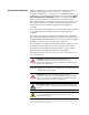


Summary of Changes
Manual Updates
The information below summarizes the changes to the PowerFlex 700H and
700S Installation Instructions, publication PFLEX-IN006, since the March
2006 release.
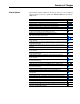
Change Page
Updated the Normal Duty power ratings Preface-1
Updated the Reference Materials List Preface-1
Added information on installations using single-phase input power 1-2
Updated the Common Bus/Precharge information 1-9
Added a description for the use of output reactors on frame 14 drives 1-2
Updated the 700H I/O board options chart 2-2
Updated the “Auto/Manual Notes” section to include information on enabling manual
mode to allow starts and jogs from the HIM in 2-wire mode
2-12
Added a note to the analog inputs on the 700S Phase II control 4-4
Added terminal wiring illustration for external brake resistor and external brake IGBT
and resistor connections on frame 9 drives
6-6
Updated all Frame 10 dimension drawings to include cable routing information. 7-1 - 7-5
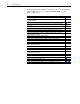
Added a dimension drawing for the frame 10 Motor Control Center (MCC), Enclosure
Codes “B” and “K”
7-4
Updated the instructions for frame 10 Ungrounded, High Resistive Ground or Grounded
B Phase Delta installations
7-9
Updated the Power Terminal Block designations for frame 10 (removed brake option
terminals)
7-14
Updated all Frame 11 dimension drawings to include cable routing information. 8-1 - 8-5
Added a dimension drawing for the frame 11 Motor Control Center (MCC), Enclosure
Codes “B” and “K”
8-4
Updated the instructions for frame 11 Ungrounded, High Resistive Ground or Grounded
B Phase Delta installations
8-9
Updated all Frame 12 dimension drawings to include cable routing information. 9-1 - 9-5
Added a dimension drawing for the frame 12 Motor Control Center (MCC), Enclosure
Codes “B” and “K”
9-4
Updated the instructions for frame 12 Ungrounded, High Resistive Ground or Grounded
B Phase Delta installations
9-9
Updated all Frame 13 dimension drawings to include cable routing information. 10-3 - 10-4
Updated the frame 13 dimensions for the NEMA/UL Type 12 - IP54 Enclosures 10-4
Updated the instructions for frame 13 Ungrounded, High Resistive Ground or Grounded
B Phase Delta installations
10-5
Added Chapter 11 - Frame 14 Installation 11-1
Updated the Agency Certification information for drives with 700H control A-1
Separated the drive ratings information from the drive protection devices - now in
separate tables
A-5,
A-13
Updated the drive rating, fusing and circuit breaker specifications A-13
Added new Appendix B to consolidate the common lifting and mounting instructions B-1
Added the Allen-Bradley 842HR rotary encoder to the list of compatible encoders C-1
Updated wiring diagrams for the Hi-Resolution Encoder C-2
Updated wiring diagrams for Resolvers D-3
Updated wiring diagrams for the MDI board E-3
Added Appendix E on ATEX Approved PowerFlex 700H Drives in Group II Category (2)
Applications with ATEX Approved Motors
F-1