
Installation manual
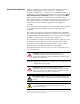


ii Summary of Changes
The information below summarizes the changes to the PowerFlex 700H and
700S Installation Instructions, publication PFLEX-IN006, since the
October, 2004 release.
Change Page
Updated the drive ratings for PowerFlex 700H and 700S Preface-1
Updated the information on installing unbalanced, ungrounded or resistive grounded
distribution systems
1-1
Added information on DC input precharge control wiring 1-10
Updated the “Control Board Slot Designations” table for the new 20C-DG1 digital I/O
option board
2-2
Added drive catalog numbers for 700H control I/O board options 2-2
Updated the “Analog Input, PTC 0-10V Input” wiring example 2-8
Added Chapter 4, “Control Wiring for PowerFlex 700S Drives with Series II Control” 4-1
Updated information on frame 9 operating temperatures 6-2
Updated frame 9 installation instructions for unbalanced, ungrounded or resistive
grounded distribution systems
6-4
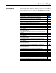
Updated frame 10 minimum mounting clearances 7-1
Updated frame 10 operating temperatures 7-2
Added dimensions drawing for frame 10 NEMA/UL Type 12 - IP54 Enclosure 7-5
Updated frame 10 “Moving Control Frame” to show slotted holes in Control Frame 7-6
Updated frame 10 “Removing Protective Covers” to omit screws that were not present. 7-8
Updated frame 10 installation instructions for unbalanced, ungrounded or resistive
grounded distribution systems
7-9
Updated frame 11 minimum mounting clearances 8-1
Updated frame 11 operating temperatures 8-2
Added dimensions drawing for frame 11 NEMA/UL Type 12 - IP54 Enclosure 8-5
Updated frame 11 installation instructions for unbalanced, ungrounded or resistive
grounded distribution systems
8-9
Added Chapter 9, “Frame 12 Installation” 9-1
Added Chapter 10, “Frame 13 Installation” 10-1
Updated the agency certifications A-1
Updated the drive protection specifications A-1
Updated the fusing and circuit breaker specifications A-13, A-13
Added specifications and wiring diagram for using the Stahltronic linear encoder E-3