
Installation manual


Hardware Features of the Mass Storage
Systems
Chapter 2
22
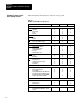
Table 2.B identifies the hardware for each mass storage system.
Table 1.C
Hardware
for Each Mass Storage System
1770-M10 1770-M11 1770-M12
Front View
Indicators
• Hard Disk
• Micro-floppy
• Power
• Restart
X
X
X
-
X
X
X
X
X
-
X
-
Pushbuttons
• Eject
• Restart
X
-
X
X
-
-
Other
• Access Slot for Micro-floppy
X X -
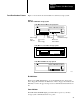
Back View
Communication Channels
• Parallel Channel Out J20
• Parallel Channel In J21
• Serial Channel J22
• Test J23
• RS422 Interface J24
X
X
-
-
-
X
-
X
X
-
X
-
-
-
X
Switches
• Power
• Baud Rate
X
-
X
X
X
-
Other
• Power Connect
• 120/220 V AC electrical card
• Fan and Filter
• Fuseholder
X
X
X
X
X
X
X
X
X
X
X
X
Internal Components
• Winchester Hard Disk Drive
• Micro-floppy Disk Drive
• Power Supply
• Disk Controller Module with Small Com-
puter Systems Interface Module (SCSI)
• Disk Memory Interface Module (DMIM)
• RS422 to SCSI Interface Module
X
X
X
X
-
-
X
X
X
X
X
-
X
-
X
X
-
X
Cables
• P/N 629678-01 (for power)
• P/N 966189-01
• P/N 966289-01
X
X
-
X
-
-
X
-
X
Program Diskette
• Operating System for PLC-3 Peripheral
Communication Module/Mass Storage
System
- X -
Hardware Features for the
Mass Storage System