Technical Reference For Allen-Bradley PLCs Merrick Industries, Inc. 10 Arthur Drive Lynn Haven, FL 32444 (850) 265-3611 Revision 1.
Revision Notes 0.70 10/02/95;LTM First complete issue 0.70A 11/08/95;LTM Typos, 20.00.K, 30.00.D, 11.00.HP Registers 0.71 01/29/96;BPM,LTM Upgraded for version 0.71 0.72 9/11/96;LTM Upgraded for version 0.72 0.73 10/04/96;RWM Upgraded for version 0.73 0.74 01/13/97;LTM Upgraded for version 0.74 0.99 03/07/98;LTM Upgraded for version 0.99 0.99 03/13/98;LTM Upgraded for version 1.10 1.11 08/31/98:RSS Added SB/MC Compatibility table 1.12 05/18/99:ldd Update Table 1.
INTRODUCTION ..............................................................................................................................1 PLC connectivity........................................................................................................................1 Control Room software connectivity .........................................................................................1 MC Controllers connectivity ...............................................................................
PLC TYPED MESSAGES...........................................................................................................20 PLC Typed Read.....................................................................................................................20 PLC Typed Write .....................................................................................................................20 PLC WORD RANGE MESSAGES ..........................................................................................
SourceAddress ....................................................................................................................44 DestAddress ........................................................................................................................44 Elements..............................................................................................................................45 DataTypes .................................................................................................
INTRODUCTION SuperBridge (SB) is a software application that provides two-way communications between Merrick MC²/MC³ controllers (MCs) and the Allen-Bradley (A-B) communication networks Data Highway Plus (DH+) and Data Highway 485 (DH485). Serial communication (DF1) between SuperBridge and a PLC is also supported. Status and variables in MCs will appear on the A-B networks as integer and floating point files in a PLC-5 or SLC500.
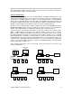
upgraded. See Model Specific Information (page 23). The system response time will improve with decreasing number of MCs connected. If very fast response times are required, more than one SB can be installed on a DH+ or DH485 network. Hardware Requirements If a PLC-5 is to be used, SB can run on an Allen-Bradley 1771-DXS2 Information Processor using a PC Flash EPROM card. If SB is to operate on the DH+ network, the 1771-DXS2 must be connected to a 1771-DXKT adapter, see figure 1 (a).
SETTING UP A SYSTEM Setting up a SB system includes the following steps: 1. Verify that existing MCs are equipped with a RS-485 Serial Ports and have software application versions listed in Model Specific Information (page 27). If not, complete and/or upgrade. 2. If an A-B 1771-DXS2 processor is used, locate a PLC-5 to serve as a host for the 1771DXS2 Information Processor and 1771-DXKT adapter (if applicable). Two slots must be free, and the power supply must be able to handle an additional 5V load of 1.
INSTALLING SB SOFTWARE AND HARDWARE If SB hardware and software are purchased entirely from Merrick, it comes installed and configured along with a specification sheet. The configuration may have to be altered as the system changes. When an A-B 1771-DXS2 or A-B 1771-EIP Information Processor is used, the software and configuration files resides on a PCMCIA Flash EPROM card. Merrick has to do the installation for the 1771-DXS2, since a BIOS upgrade in the 1771-DXS2 Information Processor is necessary.
• SIO-485 Mode. E4 = {Dip Shunt @ SIO-485}. This is not the default setting. • Line terminations on. SW-2 = {(T,P,P,L,L) = (On, On, On, Off, Off)}. For COM2, the following strappings would change to: • Port Adress to 2F8. SW1 = {On, On, Off, On} • IRQ Jumper to IRQ3. E1 = {Jumper @ 3}. Install RS-422 multiport adapter, if needed If more than 32 MCs are connected to the host PC serial port, or to increase performance, a multi-port RS-422 adapter must be used.
CONFIG.SYS \CONFIG.SYS They can all be edited with the MS-DOS editor ‘EDIT’. The default CFG_KT.INI file is seen below. It is configured for DH+ communication using a KT Card. ; CFG_KT.INI ; SuperBridge Default KT Configuration ; 10/10/95/LTM [DTL_KT.1] DEVICE=KT MEMORY=D400 IRQ=5 STATION=71 NAME=SUPERB TERMINATION=OFF Entries in CFG_KT.INI are [DTL_p.n] Device definition statement. Protocol designators (p) can be KT, 485, or DF1 depending on communication method used.
DEVICE=KTX Must be present if KTX Card is used to interface with DH+. MEMORY=D700 Must correspond to the memory address DIP switch setting on the KTX card. D700 is the default. See Install the KTX Card, if used (page 4). IRQ=5 Must correspond to the position of the IRQ jumper on the KTX card. 5 is the default. Install the KTX Card, if used (page 4). STATION=71 This is the station number for SB. See Assign Station Numbers (page 9) NAME=SUPERB This is the name that will appear on DH+ for SB.
; SuperBridge DF1 Configuration ; 11/30/95/BPM [DTL_DF1.3] DEVICE=DF1 BAUD=19200 IRQ=4 COM_PORT=1 NAME=SB_DF1 ERROR=0 PARITY=0 DUPLEX=1 Entries in CFG_KT.INI are [DTL_p.n] Device definition statement. Protocol designators (p) can be KT, 485, or DF1 depending on communication method used. Pushwheel numbers (n) may range from 1 to 8. Each communication interface module must have a unique pushwheel number. DEVICE=DF1 Must be present if DF1 communication is to be used.
C:\ABIC\BIN\CFG_485 C:\ABIC\BIN\RNATSR C:\ABIC\BIN\RNA -a8 CD SUPERB ABDRV There is normally no reason to alter this file if DH485 communication is to be used. The following is an example of AUTOEXEC.BAT configured for DF1 communication. REM AUTOEXEC.
SETTING UP COMMUNICATIONS WITH THE MCS The MC network is a four wire RS-485 Master-Slave polled communications loop. All MCs are slaves on the network, and are required to have a RS-485 serial port and a unique address, called “Controller Number” (CN). The CN is set up, along with other serial communications parameters, in each MC. SB is the master, and must have either a four wire RS-485 or a RS-422 serial port. MC Physical Connection Use a RS-422 type two pair shielded cable like Belden 9368.
3. Parity. Must be set to “NO Par” in all MCs. 4. Data Bits. Must be set to 8 in all MCs. 5. Start character. Must be set to 10 in all MCs. 6. End character. Must be set to 13 in all MCs. SB Configuration for MCs SB configuration parameters are set in SUPERB.INI. See Configuration (page 41) At least Controllers in the [Sizes] Section (page 41) must be set. The rest of the parameters could normally be left at their default settings. Note that the CN is defaulted to Controller Index + 1.
2. Check all communication parameters in all MCs. All parameters must be equal except the “Controller Number”, which must be different for all MCs. 3. Check the corresponding line parameter settings in SUPERB.INI. See [PortN] Sections (page 41). 4. All MC²s should show a blinking yellow light on the serial port, indicating that they are receiving telegrams from SB. If it does not blink at all, there are problems with the cable, SB serial port or RS-422 converter. 5. The green light should also blink.
Using SB default segment parameters is highly recommended. See [PLCDefault] Section (page 43). At least the DefaultStation (page 43) needs to be set. For complex installations with file copy to multiple PLCs, each segment can be specified in detail in the [SegmentN] Section (page 44). Connecting SB to DH+ DH+ network design is explained in [5], chapter 5. To successfully maintain a system of PLCs, SBs and MMIs, a general knowledge in this area is required.
PLC FILE SPECIFICATION MC Data in SB is available in PLC style files. They are: • N12, containing read-only bit or integer oriented data from the MCs, such as inputs, outputs, alarms and communication status. In N12, there are eight words per connected MC. • N13, containing read-write bit or integer oriented data for the MCs, containing parameter tags and function requests. In N13, there are seven words in per connected MC.
failed. Bit 5 (0020) (x_INMENU) In menu. The MC menu system is engaged. This means that the effect of any remote keycode requests are unpredictable. Bit 6 (0040) (x_STARVE) Material starvation condition. The MC is in a state of low feedrate deviation alarm. Only MCs that supports feedrate can have this bit set. It can be used to take action on a feeder material starvation condition. Bit 7 (0080) (x_RECAL) Recalibration.
MC General Alarms or Warnings, N12:3,11,19..(x_ALARMS) Any current general alarms or warnings in the MC is visible as a bit in this integer. MCs have a maximum of 16 general alarms or warnings. There is one bit per alarm. The interrogation is a part of the fast loop. To find out about MC general alarms and warnings, see General Alarms (page 24). Request Done Bits, N12:4,12,20..(x_REQDONE) This integer contains the "Done" bits for requests set by the user in the MC Request Word.
Fast Tag Register Number, N13:0,7,14..(x_FTAG) This is a numerical value of a register number in the MC. To find out about MC register numbers, see Useful Registers (page 29). If the value of this integer is not zero, the corresponding register will be polled in the fast loop. The value of the register will be available in the Fast tagged value, F14:0,8,16.. (page 19), as long as the MC is on-line and the Tag Access Problems bit in the MC Status Word, N12:0,8,16.. (page 14) is not set.
Bit 14 15 MC² keyboard key "X" "ENT" Hex Code 4000 8000 Binary Code 0100 0000 0000 0000 1000 0000 0000 0000 Possible errors bits are 0 and 3. See Request Error Bits, N12:5,13,21.. (page 16) Bit 5 (0020) (x_RGETREG) Request register contents. The numerical value of the register number must be present in the MC Request Integer Parameter N13:5,12,19.. (page 18). Upon completion, bit 5 of Request Done Bits, N12:4,12,20.. (page 16), will be set.
Fast tagged value, F14:0,8,16..(x_FTAGV) This float contains the value of the register tagged in Fast Tag Register Number, N13:0,7,14.. (page 17). The value is updated in the fast loop. Slow tagged values 1 - 3, F14:1-3,9-11,17-19..(x_STAG1V, x_STAG2v, x_STAG3V) These float contains the values of the registers tagged in Slow Tag Register Number 1 - 3 N,13:1-3,8-10,15-17.. (page 17) The values are updated in the slow loop. Process Value, F14:4,12,20..(x_PROCV) The value in this float depends on the MC model.
UNSOLICITED MESSAGES SPECIFICATION SB will act as a PLC when receiving unsolicited messages that request reading and writing data to and from the four data files. Control files (N13 and F15) can be read from and written to. Report file (N12 and F14) can only be read. Some PLC-2 unsolicited messages are also supported for backwards compatibility. A-B DH+ and DH485 messages are specified in [6]. Issuing messages that are not supported by SB will generate an extended error return message 0xF00E.
element requested is beyond the last element in the SB requested file, extended error code 0xF00A is returned. If too many (more than 100 for N13, 50 for F15) elements are requested, extended error code 0xF009 is returned. PLC Read-Modify-Write See [6], page 3.6-5. With A-B terminology, this is command 0x0F, function 0x26. Data in N13 (only) will be modified if the last element requested to be modified is within the SB file range for N13. If other files are requested, extended error code 0xF006 is returned.
PLC-2 Unprotected Read See [6], page 3.2-8. With A-B terminology, this is command 0x01. Data will be returned if the last element requested is within the SB file range for F15, mapped into a PLC-2 memory image, as described above. If other elements are requested, or the length in bytes of the requested data table is greater than 244, error code 0x50 is returned. Note that it is possible to request data that passes mapped PLC-5 file boundaries, i.e. the element following the last N13 element is F14:0.
MODEL SPECIFIC INFORMATION SuperBridge was released years after the MC² weighing controller. For some older versions of the controller software applications, full support is not available. This chapter explains limitations and application specific information that relates to specific MC² models. SUPPORTED FUNCTIONS The following table lists any limitations of SuperBridge operation in relation to different MC² models and versions. Models not listed here are not supported at all. MC² Models 20.00.K 22.00.
Note 3: See Setpoint (page 24). Note 4: An error in the 20.00.HP.O, A and B applications makes it impossible for SuperBridge to detect the fact that the controller is taken out of “Comm Setpoint Mode”. Note 5: Some scaling problems exist for some registers. If bit 6 or 7 in the register property word is set, unpredictable results can occur. See Useful Registers, page 29.
Controller 11.00.HP 20.00.HP 30.00.HP 35.00.
Controller 30.00.D 22.00 10.00.HP 11.00.HP 20.00.
Note that the status of unused digital inputs in MCs are reported to the MC Digital I/O, N12:2,10,18.. (page 15), even if they are not used by he MC application. They can be used as remote inputs for the ladder logic. INTERNAL STATE Some cyclic controller applications have an internal state variable, useful for indication of what’s going on in. The state variable is numerical, and can not be used for bit monitoring. 30.00.
State Meaning 2 3 4 5 6 Normal LIW feed Filling Stabilization time after filling Run cleanout cycle to low weight Run Cleanout cycle (time) after low State 7 8 Meaning weight Feeder Stopped A Blocking condition occurred 31.51.
State 30 Meaning Clearing the current Batch USEFUL REGISTERS All MC² applications contains a numbered table of parameters, called registers. They are useful in a SuperBridge environment for monitoring and control purposes. In the following sections, the content of the registers for the different applications are listed, along with the property word. The property word describes access rules, decimal places and scaling of the registers. The property word has the following layout: Bit 15..
DIAGNOSTIC SCREENS If a VGA compatible monitor and a PC keyboard is connected to the SB host PC, several diagnostic screens are available. They are usable for verification, troubleshooting, checking ladder and MMI programming, and for editing data in N13 and F15. Note that with the exception of the Home Screen, there is a SB performance penalty associated with the diagnostic display. For all screens in this section, the following SUPERB.INI was used: ; ; SUPERB.
THE HOME SCREEN 1 2 3 4 5 6 7 8 9 10 11 12 13 14 15 16 17 18 19 20 21 22 23 24 25 SuperBridge Home Screen Merrick - Allen-Bradley SuperBridge Copyright (C) 1996 Merrick Industries All Rights Reserved Ver 0.99 Built May 13 1998, 16:15:52 0: Run/30.00.HP.A 4: Run/11.00.HP.A 0: Run/N12:0 4: Run/N12:16 F2 MC Data Time: Started: MCs: Segments: Thu May 14 14:08:26 1998 Thu Ma4 14 14:05:24 1998 5 6 MC Status map Run/20.00.HP.C Run/30.00.HP.
MC DATA SCREEN 1 2 3 4 5 6 7 8 9 10 11 12 13 14 15 16 17 18 19 20 21 22 23 24 25 MC Data, Controller Index 2 Number of MCs configured MC in use (1 = YES, 0 = NO) MC WatchDog (0.
Line Keyword 7 MC Current Status 9-11 IR Elems 1215 IC Elems 1619 1215 FR Elems FC Elems Explanation and version is unknown to SB (not supported) Possible status are Running (running, no communication problems), OffLine (taken off-line), NotUsed, Reviving (communications reviving attempt in progress) and CommErr (Communication problems). Integer Report data from N12. Integer Report File, N12 (page 14). Hexadecimal representation. “Pending” means actual current data in SB.
MC Combined Diagnostic Screen 1 2 3 4 5 6 7 8 9 10 11 12 13 14 15 16 17 18 19 20 21 22 23 24 25 MC Combined Diagnostic Port 0 Controller Index 0 RxPtr: 0 TxPtr: 6 Used ParErrs Timeouts BadataErrs ErrErrs MaxRetries RxData: 30000000000000000006d TxData: 2d6a 1¦State 3¦LastErr 0¦OvrErrs 1¦FrameErrs 6¦CsumErrs 0¦BusyErrs 0¦FormatErrs 0¦RFrmErrs 0¦CurrSlave 1¦CurrTelegram 2¦PortIndex 0¦ActiveMC 0¦FatalErrs 0¦BreakErrs 0¦AccessErrs 0¦RLimErrs 7¦TimerTicks 1¦UART IIR 1¦LastFatErr 0¦BufOverrs 0¦BadFncErrs 0¦No
Line Keyword 14 ModelIdx 14 Pacing 15 UnitAddress 16 Errors 16 LastErr 16 FatalErrs 16 LastFatalErr 16 DownTime 17 RevTime 17 InPuts 17 OutPuts 17 Alarms 17 NumRegs 18 18 18 18 19 20 20 SetDlsa SetDlsc LastSp Leylocked DecimalPoints Total ProcV 21 Bezel 21 YLed 21 GLed Explanation even if the specific version is not supported by SB. A 0 here indicates that there is no support for this application/version combination. The controller is in pace mode.
F1 Switch to The Home Screen (page 31) F2 Switch to A-B File Copy Diagnostic Screen (page 37) F3 Switch to MC Data Screen (page 32) F4 Switch to port data for the next serial port F4 Switch to port data for the previous serial port F6 Switch to the MC with the next controller index F7 Switch to the MC with the previous controller index F10 Stop SB and return to the DOS prompt Numerical Error Values This is a list of the numerical values that can appear in a communication error field: Value 2
A-B FILE COPY DIAGNOSTIC SCREEN 1 2 3 4 5 6 7 8 9 10 11 12 13 14 15 16 17 18 19 20 21 22 23 24 25 A-B File Copy Diagnostics ErrCall: ErrMsg: Events ExitFlag DTL_I_SUCCESS, Operation Successful 1|Wtrs 922|LastState 66|LastError 0|WMask 00000002|RMask 00000000|MaskBits Seg SrcAddr DesAddr El DType Access 0 N12:0 N12:0 40 WORD MODIFY 1 N13:0 N13:0 35 WORD READ 2 F14:0 F14:0 40 FLOAT MODIFY 3 F15:0 F15:0 15 FLOAT READ 4 N12:16 N12:0 24 WORD MODIFY 5 F14:16 F14:0 24 RAW MODIFY F1 Home Screen F2 A-B Msgs F3
Parameter Explanation Rejects How many file transfer attempts that has been rejected since SB was started. LastBad I/O status for the latest rejected file transfer attempt. Time Transfer time in ms for the last file transfer Function keys: F1 Switch to The Home Screen (page 31) F2 Switch to A-B Unsolicited Messages Diagnostic Screen (page 39) F3 Switch to MC Combined Diagnostic Screen (page 34) F4 Switch to next page of segment information. No effect if all segment lines fit on one page.
A-B UNSOLICITED MESSAGES DIAGNOSTIC SCREEN 1 2 3 4 5 6 7 8 9 10 11 12 13 14 15 16 17 18 19 20 21 22 23 24 25 A-B Unsolicited Messages Diagnostics Telegrams ExitFlag Stn Stn Stn Stn Stn Stn Stn Stn Stn Stn Stn Stn Stn Stn Stn Stn 041. 041. 041. 041. 041. 041. 041. 041. 041. 060. 041. 060. 041. 060. 041. 041.
Unsolicited Messages Specification (page 19), which A-B data file was requested and the number of elements. A row for a bad message contains requesting station number in octal representation, the length (in bytes) of the message, the error return code issued, see Error Codes Returned (page 22), and the message body itself, starting with the A-B command in hex.
CONFIGURATION SB is completely configurable via the configuration file, SUPERB.INI. The file can be edited using a text editor. It is loaded every time the SB application is started up. The file is divided into sections with a format similar to Windows initializations files. [SIZES] SECTION The sizes section deals with the size of the SB application, such as number of connected MCs. ComPorts Depending on how many MCs are connected, one or more RS-422 serial ports are used for the MC connections.
UartBase Base address for the UART, port N, hexadecimal. Default is 2F8 for section [Port0], which is the base address for COM2 in a normal PC. COM1 has normally base address 3F8. Sections [Port1]..[Port3] does not have a default; the base address for those ports have to be specified when a multiport adapter is used. DLABReg This entry indirectly specifies the baud rate used for each port. It is possible to run different ports with different baud rates.
Port The index of the serial port to which the controller in connected. If a single serial port is used, do add a port entry. Valid entries are 0..ComPorts - 1. [ABDATA] SECTION For applications where there is no PLC-based control file, initial data can be set for every element in N13 and F15. This is typically done for register tags, setpoints and other control information. Default is that all elements of N13 and F15 are initialized to zero.
Segment 10 11 12 13 14 15 MCPerSegment = 3 First Element F14:48 F15:18 N12:72 N13:63 F14:72 F15:27 Elements 24 9 24 21 24 9 Segment 10 11 MCPerSegment = 5 First Element F14:80 F15:30 Elements 16 6 DefaultProcessor The default PLC type for the target PLC. Valid entries are PLC5 and SLC500. If no Processor entry exist in the [SegmentN] Section (page 44), this processor type is assumed. Default is PLC5. [SEGMENTN] SECTION This section contains entries for the A-B file copy map. N is the segment index.
Elements Number of elements for segment N. Max 100 for N files, 50 for F files. DataTypes Valid entries are FLOAT, WORD and RAW. Use WORD for N files. If the target PLC is a PLC-5, use FLOAT for F files. If the target PLC is a SLC500, use RAW for F files. Access Use MODIFY for source files N12 and F14. Use READ for source files N13 and F15. PortID This identifies the port through which the server communicates across the network.
PLC2Base This is the PLC-2 address, in octal format, where the first SB file element (N12:0) is located. Default is 200 (oct). To calculate the PLC-2 address for other elements, see PLC-2 Unprotected Messages (page 21). Use the A-B Unsolicited Messages Diagnostic Screen (page 40) to verify that the PLC-2 address used returns the data intended. PLC2ReverseFloat This parameter determins the encoding of a PLC-2 representation of a floating point number. Possible values are: 0 Default.
[MC3] Port = 1 ; MC4 and MC5 are connented to the third port. [MC4] Port = 2 [MC5] Port = 2 ; MC6 and MC7 are connented to the fourth port.
REFERENCES [1] 1771 Information Processor User Manual Allen-Bradley Publication 1771-6.5.100, December 1992 [2] Communication Interface Module Installation Data Allen-Bradley Publication 1784-2.31, August 1993 [3] 1785 PLC-5 Family Programmable Controllers Hardware Installation Manual Allen-Bradley Publication 1785-6.6.1, June 1993 [4] PLC-5 Programming Software, Software Configuration and Maintenance Allen-Bradley Publication 6200-6.4.