ALLEN-BRADLEY AtomScan Bar Code Scanner (Catalog No.
Important User Information Solid state equipment has operational characteristics differing from those of electromechanical equipment. “Safety Guidelines for the Application, Installation and Maintenance of Solid State Controls” (Publication SGI-1.1) describes some important differences between solid state equipment and hard–wired electromechanical devices.
Table of Contents AtomScan User Manual User Manual Using This Manual Chapter 1 Chapter Objectives . . . . . . . . . . . . . . . . . . . . . . . . . . . . . . . . . . . . . . . . . What You Need to Know . . . . . . . . . . . . . . . . . . . . . . . . . . . . . . . . . . . . Convention Used . . . . . . . . . . . . . . . . . . . . . . . . . . . . . . . . . . . . . . . . . . Contents of Manual . . . . . . . . . . . . . . . . . . . . . . . . . . . . . . . . . . . . . . . . Terminology . . . . . . . . . . . . .
Table of Contents AtomScan User Manual User Manual Installing the AtomScan Scanner Operating the Scanner Chapter 4 Chapter Objectives . . . . . . . . . . . . . . . . . . . . . . . . . . . . . . . . . . . . . . . . . Environmental Considerations . . . . . . . . . . . . . . . . . . . . . . . . . . . . . . . Aiming AtomScan . . . . . . . . . . . . . . . . . . . . . . . . . . . . . . . . . . . . . . . . . Mounting Operations . . . . . . . . . . . . . . . . . . . . . . . . . . . . . . . . . . . . . . .
Chapter A–B 1 Using this Manual Chapter Objectives This chapter gives an overview of the manual, including: • • • • • Contents of manual What you need to know Conventions and terminology Laser warning symbol Related publications What You Need to Know No special knowledge is required to read this manual. Some knowledge of trigonometry and solving simple equations is helpful in operating the scanner. Convention Used In this manual, the Catalog No.
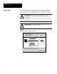
Chapter 1 Using this Manual Laser Warning Symbol AtomScan scanners are Class II Laser Devices as specified by the Center for Detection of Radiation Hazards (CDRH). Momentary exposure to Class II laser light is not known to be harmful. However, • do not stare at the laser light. • do not look into the scanner window when the mirror is not spinning. The steady beam of laser light could possibly injure your eye. CAUTION: This laser caution symbol is required where laser radiation is present.
Chapter A–B 2 AtomScan Product Family Chapter Objectives This chapter gives an overview of features and accessories of AtomScan scanners: • • • • Overview of Scanner Overview of the AtomScan scanner reading system Choosing an AtomScan scanner Available decoders and accessories Package detector and extension cables The AtomScan scanner uses a visible laser diode for non-contact reading of bar code symbols. The laser generates a small, concentrated light beam.
Chapter 2 AtomScan Product Family Safety Labels The scanners use a low power visible laser diode. As with any bright light source, such as the sun, you should avoid staring directly into the beam. Momentary exposure to a CDRH Class II laser is not known to be harmful. ! ! ATTENTION: The laser beam can be harmful to eyesight. Avoid direct eye contact with the laser beam when the mirror is not spinning Avoid prolonged eye contact with the laser beam when the mirror is spinning.
Chapter 2 AtomScan Product Family Overview of Scanner Features of AtomScan scanners include: • low power consumption • wide field of view • the ability to read a wide range of bar code densities. Note: Bar code density is the width of the narrowest bar or space.
Chapter 2 AtomScan Product Family Accessories AtomScan scanners require an adapter and a cable to connect with an Enhanced Decoder. The scanners are compatible with these Allen-Bradley bar code decoders: • Catalog No. 2755-DS1A Enhanced Single-Head Decoder • Catalog No. 2755-DD1A Enhanced Dual-Head Decoder The gasketed enclosure is equipped with a NEMA Type 1 connector, so it is suitable for a wide range of applications.
Chapter 2 AtomScan Product Family Package Detectors A Package Detector is used to sense when a package containing a bar code symbol is in position to have that symbol scanned and decoded. Allen-Bradley PhotoswitchR retro-reflective photoswitches, Series 6000 or Series 9000 with the QD (Quick Disconnect) option are recommended. The QD option provides a Micro-Change connector compatible with the connector on the Adapter Module (2755-NC18).
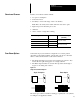
Chapter A–B 3 Designing the System Chapter Objectives This chapter provides information needed to set up the scanner correctly, including: • Bar code symbols • Symbol orientation • Selecting the appropriate AtomScan scanner for your application Setup Goals Each application must be evaluated carefully. Successful bar code scanning begins with quality bar code symbols, and the correct number, type, and location of scanners, decoders, and object sensors.
Chapter 3 Designing the System Bar Code Symbols There are two basic types of bar code symbols. One-dimensional The one-dimensional bar code symbols have one row of bars and spaces. These were among the first to be developed.
Chapter 3 Designing the System Bar Code Symbol Length and Height When measuring a symbol, orientation must be ignored. Its height is measured from one end of a bar to the other, and its length is always the distance from one end of the symbol to the other, including the “Quiet Zones”. A Quiet Zone is the empty space before or after the bars, and is usually equal to 10 times the Narrow Element Width. Figure 3.
Chapter 3 Designing the System Symbol Orientation Bar code symbols must be in the correct position as they move by the scanner. The scan line must cross every bar, space, and both quiet zones on the same sweep. Correct: All bars are crossed by scan line Not Correct: Some bars are not crossed by scan line Picket Fence and Step Ladder Orientation The primary orientation of the bar code symbol can be either picket fence or step ladder.
Chapter 3 Designing the System Figure 3.3 Step Ladder Orientation Direction of Travel Scanner Mounted On Side of Conveyor Direction of Travel Scanner Mounted Above Conveyor In general, ladder orientation (Figure 3.3) is preferred, because each scan covers a slightly different part of the symbol. This means that: • imperfections in the symbol are less liable to prevent a successful read. • symbol placement is not as critical. In picket fence orientation (Figure 3.
Chapter 3 Designing the System Tilt, Pitch, and Skew The AtomScan scanner can read a symbol correctly even if the symbol or package is not correctly oriented. Figure 3.4 shows several possible positions. Figure 3.4 Positioning Terminology Pitched package and symbol Skewed package and symbol Tilted symbol Correctly positioned symbol and package • Tilt: A symbol is tilted when the symbol’s bars are not 90° to the scan line.
Chapter 3 Designing the System Figure 3.5 Correct Setup of Scanner 20_-30_ Scanner between 20_ and 30_ above or below the symbol 20_-30_ When using “A” range scanners to read symbols with high paper noise, increasing the skew to 30° may enhance performance. Selecting the Correct AtomScan Scanner To select the correct AtomScan scanner for your application, you must measure: • the distance between the scanner and the symbol (which must be within the Read Range) • the apparent Narrow Element width.
Chapter 3 Designing the System Determining the Read Range The Read Range is the distance from the face of the scanner over which a bar code symbol can be read reliably. Read Range varies with: • the bar code symbol’s Narrow Element width • bar code symbol quality, including print contrast In picket fence applications the scanner and symbol are usually set as far apart as possible within the Read Range, to give the greatest number of scans per symbol. Table 3.
Chapter 3 Designing the System Table 3.A and Table 3.B show the relationship among the symbol density (width of the narrowest bar or space), the Read Range, and the usable scan width. The performance may vary slightly for raster units. Figure 3.6 gives the same information as Table 3.A in graphic form. Figure 3.6 Read Range vs. Narrow Element Width mm 1.25 Mils (.001 in.) 50 45 Apparent Minimum Element Width 1.00 40 35 .75 30 “B” 25 .50 20 15 .
Chapter 3 Designing the System Raster Height A raster scanner is used when the bar code symbol is of poor quality: • symbols printed on a dot matrix printer • bars and spaces not uniform • bars have voids or spaces have spots The raster scanner puts lines through ten locations in the symbol, which increases the probability of finding a location that can be reliably decoded. The Raster Height is the distance between the raster scan lines farthest apart at a given distance from the scanner.
Chapter 3 Designing the System Picket Fence Applications To calculate minimum scans per symbol, use this formula: S = S = R= W= L = C= R (W–L) C (must be at least 5) Scans per label Scan Rate Scan Width at the minimum read distance Symbol Length (including quiet zones) Conveyor Speed Scan Width, Symbol Length, and Conveyor Speed must be expressed in similar units. Calculations assume that the scanner and decoder are triggered for the entire time the symbol is present and the symbol has a 0° pitch.
Chapter 3 Designing the System Step Ladder Applications To calculate scans per symbol for step ladder applications, use this formula: S = S R H C = = = = RxH C Scans per Symbol (must be at least 5) Scan Rate Symbol Height (length of bars of the symbol) Conveyor Speed Conveyor Speed and Symbol Height must be expressed in similar units. Calculations assume that the scanner and decoder are triggered for the entire time the symbol is present and the symbol has a 0° pitch.
Chapter 3 Designing the System Compensating for Pitched Symbols When a symbol is pitched, the bars appear to the scanner to be narrower and closer together than if it faced the scanner squarely. For pitched symbols, you must allow for the following: • The apparent Narrow Element width, rather than the actual Narrow Element width, must be used in determining the Read Range. • The nearest and farthest symbol elements must be within the scanner’s Read Range.
Chapter 3 Designing the System Example: A 10 mil (0.25 mm) symbol including Quiet Zones is 3 inches (7.6 cm) long. It is pitched at 30_. What difference does this make in placing the scanner and in reading the symbol? Two factors reduce the Read Range of the scanner with respect to a pitched symbol: 1. the apparent Narrow Element width is first used with Table 3.A or Figure 3.6 to give the useable Read Range 2.
Chapter 3 Designing the System Table 3.C Cosines and Tangents for Various Pitch Angles Use for Apparent Narrow Element Use for Lost Read Distance Pitch Angle = Θ Cosine (Θ) Pitch Angle = Θ Tangent (Θ) 0 5 10 15 20 25 30 35 40 45 50 1.0 .996 .985 .966 .940 .906 .866 .819 .766 .707 .643 0 5 10 15 20 25 30 35 40 45 50 0 .087 .176 .268 .364 .466 .577 .700 .839 1. 1.192 Step 2.
Chapter 3 Designing the System Step 1 + Step 2. With both of these aspects working together, the Read Range is shorter with a pitched symbol than with one that is not pitched. This results in: a smaller depth of field, the region within which the symbol must be located if it is to be read. a smaller scan width, which is required in the formula for calculating the number of scans in picket fence orientation. In Figure 3.9, if the farther end of the symbol extends past 6.5” (16.
Chapter A–B 4 Installing the AtomScan Scanner Chapter Objectives This chapter provides the information needed to mount, wire, and correctly aim the scanner. The following subjects are covered: • • • • • Environmental Issues Aiming the scanner Mounting Options Package Sensor Orientation Connecting the Scanner and Package Sensor Environmental Considerations The AtomScan scanner is totally enclosed. It can tolerate light dust. However it is not designed for use in harsh environments such as wash-down.
Chapter 4 Installing the Scanner Mounting Operations The scanner can be mounted either from the bottom, or from the top with the optional mounting plate. The only tool you need for installation is a screwdriver. Note: The scanner must be located in a dry place, away from sunlight or bright light from any source. The decoder is mounted separately from the scanner. So is the package sensor, if used. The thickness of the mounting surface determines the length of the four #6-32 screws required.
Chapter 4 Installing the Scanner • If you do not use the mounting plate, use the measurements given in Figure 4.2 to locate centers of mounting holes. Drill four 5/32 inch (4 mm) holes. Note: If you use the mounting plate, refer to Figure 4.3. Mount the scanner directly to the four inner holes on the plate, and use the four perimeter holes for mounting the plate to its work location.. Using the Mounting Plate The Mounting Plate (Catalog No. 2755-NM7) allows mounting on any flat surface. 3.3 in 83.
Chapter 4 Installing the Scanner Connecting Equipment The scanner is connected to the Enhanced Decoder through the Adapter Module. The scanner cable is plugged into the Adapter Module, and then into the scanner. Cables are available in 10-foot and 15-foot lengths, so mount the decoder within that distance. Use the steps below as a guideline when connecting equipment. 1. Make sure that power to the decoder is TURNED OFF. ! ATTENTION: Do NOT connect or disconnect scanner when the decoder has power on. 2.
Chapter 4 Installing the Scanner Package Sensor Orientation A package sensor may be used to trigger the scanner and decoder. It must be placed so that it is tripped for the entire time that the bar code symbol is in the scan line. The sensor may remain tripped even after the symbol has moved on, but it must go OFF and then back ON to trigger the next package. Use the following guidelines when installing the package sensor.
Chapter 4 Installing the Scanner Connecting the Package Sensor Chapter 2 gives the information needed to select a retro-reflective photo switch, and also lists the extension cable options. The Adapter Module has a yellow stub cable with a Micro-Change connector. The extension cable is connected to the Adapter Module’s connector, and then to the connector on the sensor. In case the sensor does not have a connector, the pinout is given in Table 4.A.
Chapter A–B 5 Operating the Scanner Chapter Objectives This chapter provides information on how to set up and operate the AtomScan bar code scanner. This includes: • • • • Laser Safety Laser Safety Laser-On Indicator Turning the Laser Light OFF and ON Verifying Operation All products that emit laser light have a safety label attached, as required by Federal law. It is meant to provide basic information about the potential hazards of laser light.
Chapter 5 Operating the Scanner ! ATTENTION: If during operation an intense dot of light is generated instead of a thin line of light, immediately remove power from decoder and replace the scanner. CAUTION: Do not stare into laser beam to avoid damage to your eyes. ! ATTENTION: The scanner contains no user-serviceable parts. Laser safety regulations require that only people with the proper training can open the housing. Laser On Indicator Laser light is difficult to see.
Chapter 5 Operating the Scanner Verifying Operation 1. Place the bar code symbol where it can be read. 2. Assure that the scan line crosses all the bars and both quiet zones. Set up the Enhanced Decoder to read the symbology of your bar code label. 3. Set it for “Continuous Trigger”, and monitor the “Decoder Performance”. 4. If the decoder is properly set for the symbology, and if the scanner is aimed according to the instructions in this manual, the Decoder Performance should be at or near 100%.
Chapter A–B 6 Maintenance and Troubleshooting Chapter Objectives This chapter provides information necessary to maintain your scanner. These topics are covered: • Cleaning the windows • If the Scanner does not scan • If the Decoder does not decode Cleaning the Scan Windows For optimum performance the scan and return signal windows should be clean. When they are clean, you will barely see the reflection of the laser beam on the window. To clean the scan window: 1. Turn the decoder OFF.
Chapter 6 Troubleshooting and Maintenance Troubleshooting This section lists problems that may occur with the scanner and/or connected decoder. Each problem lists possible causes and solutions. If the scanner does not scan, go down this list in order: 1. Verify that power is applied to the decoder. 2. Verify the connections to the scanner. Note: Do not unplug the scanner cable until you have checked that power to the decoder is cut off. 3. Set the decoder for the laser light to be “Always ON”. 4.
A Appendix Specifications Laser Specifications Wavelength 670 nm nominal Safety Class CDRH Class II Operating Life 50,000 hrs. @ 25_ C Scanning Parameters Scan Type Rotating 10-sided mirror Scan Rate 330 scans per second Scan Angle 60_ Pitch "50_ maximum Skew "40_ maximum Operating Range 1 to 10 inches from the front window (See Table 3.A) Scan line Width 8.5 inches at an 8-inch distance (21.
Index A Adapter Module See also System Catalog No., 2–4 Setup Diagram, 2–4 C Cables, Catalog Nos., 2–4 Cleaning, Scanner Window, 6–1 D Decoder See also System 2755–DD1A/DD4A, Catalog Number, 2–4 2755–DS/DD, Manual Catalog Number, 1–2 2755–DS1A/DS4A, Catalog Number, 2–4 Detectors See also System Cable Options, 2–5 Photoswitch Series 600/900, Catalog Nos.
Index S Safety, Warnings, 2–2, 5–3 Scan Width Define, 3–8 Read Ranges, 3–8 to 9 Scanner Cleaning Window, 6–1 Features, 2–3 Installation, 4–1 to 6 Mounting, 4–2 to 4 Options, 2–3 Skewed, 3–7 Specifications, A-1 Summary, 2–1 Skew Summary, 3–6 Index – 2 To Improve Read, 3–7 Specifications, A-1 Step Ladder.
Allen-Bradley has been helping its customers improve productivity and quality for 90 years. A-B designs, manufactures and supports a broad range of control and automation products worldwide. They include logic processors, power and motion control devices, man-machine interfaces and sensors. Allen-Bradley is a subsidiary of Rockwell International, one of the world’s leading technology companies. With major offices worldwide.