POINT I/O EtherNet/IP Adapter Module Catalog Number 1734-AENT User Manual
Important User Information Solid state equipment has operational characteristics differing from those of electromechanical equipment. Safety Guidelines for the Application, Installation and Maintenance of Solid State Controls (publication SGI-1.1 available from your local Rockwell Automation sales office or online at http://literature.rockwellautomation.com) describes some important differences between solid state equipment and hard-wired electromechanical devices.
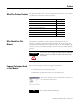
Preface What This Preface Contains Who Should Use This Manual This preface describes how to use this manual. See the table for a list of where to find specific information within this chapter.
iv Preface How to Use This Manual This manual contains an overview of the 1734-AENT adapter. It describes how to install and configure the adapter and provides examples showing how to use the adapter to communicate with POINT I/O modules over an EtherNet/IP network. About the Example Applications This manual presents two example applications that demonstrate the procedures for configuring and communicating with POINT I/O modules using the 1734-AENT adapter.
Preface v System Components We used the following components for the example applications. You need the same or similar components to set up your own control system using POINT I/O modules on an EtherNet/IP network.
vi Preface Where to Find More Information For Information About Refer to the following Rockwell publications as needed for additional help when setting up and using your EtherNet/IP network.
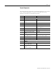
Preface For Information About See This Publication Publication Number POINT I/O 2 relay output module POINT I/O 2 Relay Output Module Installation Instructions (OX2) 1734-IN587 vii POINT I/O 2 Relay Output Module Installation Instructions (OW2) 1734-IN055 POINT I/O synchronous serial interface POINT I/O Synchronous Serial Interface Absolute Encoder absolute encoder module Module Installation Instructions 1734-UM007 POINT I/O cold junction compensation wiring base assembly POINT I/O Cold Junction
viii Preface Term Definition CSMA/CD Carrier sense multiple access/collision detection is the access method used in Ethernet. When a device wants to gain access to the network, it checks to see if the network is quiet (senses the carrier). If it is not, it waits a random amount of time before retrying. If the network is quiet and two devices access the line at exactly the same time, their signals collide.
Preface ix Term Definition Hardware address Each Ethernet device has a unique hardware address (sometimes called a MAC address) that is 48 bits. The address appears as six digits separated by colons (such as, xx:xx:xx:xx:xx:xx). Each digit has a value between 0 and 255 (0x00 to 0xFF). This address is assigned in the hardware and cannot be changed. The hardware address is required to identify the device if you are using a BOOTP utility.
x Preface Publication 1734-UM011D-EN-P - May 2011 Term Definition TCP/IP The transmission control protocol/internet protocol is a transport-layer protocol (TCP) and a network-layer protocol (IP) commonly used for communication within networks and across internetworks. Transaction An exchange of request and data and response and data. UDP The user datagram protocol (UDP) is a transport protocol that provides a very simple but fast capability to send datagrams between two devices.
Table of Contents Preface Summary of Changes Important User Information . . . . . . . . . . . . . . . . . . . . . . . . . . . . . . . . . . ii What This Preface Contains . . . . . . . . . . . . . . . . . . . . . . . . . . . . . . . . . .iii Who Should Use This Manual. . . . . . . . . . . . . . . . . . . . . . . . . . . . . . . . .iii Common Techniques Used in This Manual . . . . . . . . . . . . . . . . . . . . . .iii How To Use This Manual . . . . . . . . . . . . . . . . . . . . . . . . . . . . . . . . .
xii Chapter 4 Configure the Adapter for Direct Connection in RSLogix 5000 Software What This Chapter Contains . . . . . . . . . . . . . . . . . . . . . . . . . . . . . . . . . 25 Set Up the Hardware . . . . . . . . . . . . . . . . . . . . . . . . . . . . . . . . . . . . . . . 25 Create the Example Application . . . . . . . . . . . . . . . . . . . . . . . . . . . . . . 26 Configure the I/O . . . . . . . . . . . . . . . . . . . . . . . . . . . . . . . . . . . . . . . . .
xiii Configure the RSLinx Ethernet Communication Driver What This Appendix Contains . . . . . . . . . . . . . . . . . . . . . . . . . . . . . . . 87 Install the RSLinx Software . . . . . . . . . . . . . . . . . . . . . . . . . . . . . . . . . . 87 Configure the AB_ETH/IP Driver . . . . . . . . . . . . . . . . . . . . . . . . . . . 88 Appendix C 1734 POINT I/O Module/RSLogix 5000 Controller Tag Reference What This Appendix Contains . . . . . . . . . . . . . . . . . . . . . . . . . . . . . . .
xiv Notes: Publication 1734-UM011D-EN-P - May 2011
Summary of Changes This publication contains new and revised information not in the last release. New and Revised Information See the table for a summary of the major changes in this manual.
xvi Summary of Changes Notes: Publication 1734-UM011D-EN-P - May 2011
Chapter 1 About the Adapter What This Chapter Contains This chapter provides an overview of the 1734-AENT POINT I/O EtherNet/IP adapter, its primary features, and how to use it. You need to understand the concepts discussed in this chapter to configure your adapter and use it in an EtherNet/IP control system. See the table for a list of where to find specific information in this chapter.
2 About the Adapter The default setting for the chassis size is 1 slot, which represents the adapter by itself. Set the chassis size as the sum of the slot of the adapter plus the slots of each I/O module in the adapter backplane. For example, the adapter plus 4 I/O modules uses a chassis size of 5. The adapter stores this chassis size setting in non-volatile storage.
About the Adapter 3 • A correct POINT I/O system does not have any empty terminal bases. • After you cycle power, the adapter does not run any I/O until the number of modules comprising the chassis equals the stored chassis size. – Because the adapter cannot detect empty terminal bases, it cannot assume any safe operation until there is a match between the number of modules indicating their presence in the chassis and what the adapter has saved in non-volatile memory.
4 About the Adapter Cycle Power To a System for the First Time When you cycle power to the POINT I/O for the first time, the adapter must assign addresses to every module in the backplane. POINT I/O modules all ship configured at the same address. When you first apply power, we expect that all but one module on the backplane exhibits a solid red Module Status LED. One by one the adapter resets these modules and addresses them appropriately.
About the Adapter Hardware/Software Compatibility What the Adapter Does 5 The 1734-AENT adapter and the applications described in this manual are compatible with the following firmware revisions and software releases. Contact Rockwell Automation if you need software or firmware upgrades to use this equipment. Product Firmware Revision/ Software Release 1734-AENT adapter 1.xx or later 1756-ENBT module 2.3 or later Logix 5555 controller 11 or later RSLogix 5000 software 11.
6 About the Adapter • You maintain full control over the route taken by each message, which enables you to select alternative paths for the same end device. Understand the Producer/Consumer Model The CIP producer/consumer networking model replaces the old source/destination (master/slave) model. The producer/consumer model reduces network traffic and increases speed of transmission. In traditional I/O systems, controllers poll input modules to obtain their input status.
About the Adapter Support of Rack-optimized and Direct Connections 7 The 1734-AENT adapter supports both direct and rack-optimized connections. A direct connection is a real-time data transfer link between the controller and whatever module occupies the slot that the configuration data references. Direct connection messaging occurs at a cyclic rate specified by the RPI during configuration.
8 About the Adapter Before You Begin To effectively use your adapter, note the following considerations. Determine Compatibility If using the adapter with a 1756-ENBT module or 1788-ENBT module, use the following required firmware revisions for these bridge modules: • 1756-ENBT firmware revision 2.3 or later • 1788-ENBT firmware revision 1.33 or later If you use the BootP Utility to assign IP addresses to the adapter, use revision 2.3.2 or later.
Chapter 2 Install the Adapter What This Chapter Contains This chapter describes how to physically install the adapter on the DIN rail and connect it to the EtherNet/IP network. The following table lists where to find specific information.
10 Install the Adapter Mount the Adapter on a DIN Rail Before Installing Modules Use the following procedure to mount the adapter on a new system before you install any I/O modules. 43520 1. Position the adapter vertically above the DIN rail. 2. Press down firmly to install the adapter on the DIN rail, noting that the locking mechanism locks the adapter to the DIN rail. 3. Set the network address thumbwheel switches to the desired value. For more information, see Set the Network Address on page 19.
Install the Adapter Mount or Replace the Adapter to an Existing System 11 Follow these steps to mount or replace an adapter. 1. Remove the existing adapter (if there is one) from the DIN rail as follows: a. b. c. d. Pull up on the RTB removal handle to remove the terminal block. Disconnect the Ethernet connector from the adapter. Remove the adjacent module from its base. Use a small-bladed screwdriver to rotate the DIN-RAIL locking screw to a vertical position. This releases the locking mechanism. e.
12 Install the Adapter Wire Your Adapter Refer to the illustration to wire the adapter. WARNING If you connect or disconnect wiring while the field-side power is on, an electrical arc can occur. This could cause an explosion in hazardous location installations. Be sure that power is removed or the area is nonhazardous before proceeding.
Install the Adapter Mounting Dimensions 13 Refer to the figure for mounting dimensions. millimeters (inches) 54.9 (2.16) 76.5 (3.0) 133.4 (5.25) 36.51 (1.44) B A 43520 A = DIN rail B = Secure DIN rail approximately every 200 mm (7.8 in.) 1734-AENT 76.2H x 54.9W x 133.4D (3.0H x 2.16W x 5.
14 Install the Adapter Notes: Publication 1734-UM011D-EN-P - May 2011
Chapter 3 Configure the Adapter for Your EtherNet/IP Network What This Chapter Contains Before using your adapter in an EtherNet/IP network, configure it with an IP address, subnet mask, and optional Gateway address. This chapter describes these configuration requirements and the procedures for providing them. Here are ways you can do this: • Use the Rockwell BootP utility, version 2.3 or later, that ships with RSLogix 5000 or RSLinx software.
16 Configure the Adapter for Your EtherNet/IP Network Configuration Requirements Before you can use your adapter, you must configure its IP address, its subnet mask, and, optionally, gateway address. You can use the Rockwell BootP utility, version 2.3 or later, to perform the configuration. You can also use a DHCP server or the network address switches to configure these parameters.
Configure the Adapter for Your EtherNet/IP Network 17 IP Address The IP address identifies each node on the IP network (or system of connected networks). Each TCP/IP node on a network (including the 1734-AENT adapter) must have a unique IP address. The IP address is 32 bits long and has a net ID part and Host ID part. Networks are classified A, B, C, (or other). The class of the network determines how an IP address is formatted.
18 Configure the Adapter for Your EtherNet/IP Network When a node needs to communicate with a node on another network, a gateway transfers the data between the two networks. The figure shows gateway G connecting Network 1 with Network 2. A 128.1.0.1 Network 1 128.1.0.2 G B C 128.2.0.1 128.2.0.3 128.2.0.2 Network 2 When host B with IP address 128.2.0.1 communicates with host C, it knows from C’s IP address that C is on the same network.
Configure the Adapter for Your EtherNet/IP Network 19 The new configuration is: A 128.1.0.1 Network 1 128.1.0.2 G B 128.2.64.3 128.2.64.1 128.2.64.2 Network 2.1 G2 D 128.2.128.1 128.2.128.2 Network 2.2 128.2.128.3 A second network with Hosts D and E was added. Gateway G2 connects Network 2.1 with Network 2.2. Hosts D and E will use Gateway G2 to communicate with hosts not on Network 2.2. Hosts B and C will use Gateway G to communicate with hosts not on Network 2.1.
20 Configure the Adapter for Your EtherNet/IP Network The adapter reads the thumbwheel switches only when you cycle power to determine if the switches are set to a valid number. Press either the + or buttons to change the number. Valid settings range from 001 to 254. When the switches are set to a valid number, the adapter’s IP address will be 192.168.1.xxx (where xxx represents the number set on the switches). The adapter’s subnet mask will be 255.255.255.0 and the gateway address is set to 0.0.0.0.
Configure the Adapter for Your EtherNet/IP Network 21 2. Double-click the hardware address of the device you want to configure. You see the New Entry dialog with the device’s Ethernet Address (MAC). 3. Enter the IP Address you want to assign to the device, and click OK. The device is added to the Relation List, displaying the Ethernet Address (MAC) and corresponding IP Address, Hostname, and Description (if applicable).
22 Configure the Adapter for Your EtherNet/IP Network You must have an entry for the device in the Relation List panel to re-enable DHCP. Save the Relation List You can save the Relation List to use later. To save the Relation List perform the following steps: 1. Select Save As... from the File menu.
Configure the Adapter for Your EtherNet/IP Network 23 The Save As dialog appears. 2. Select the folder you want to save to. 3. Enter a file name for the Relation List (for example, control system configuration), and click Save. You can leave the Save as type at the default setting: Bootp Config Files (*.bpc). You can then open the file containing the Relation List at a later session.
24 Configure the Adapter for Your EtherNet/IP Network To configure the adapter with a fixed IP address, see Configure the Adapter with Fixed IP Address on page 43. ATTENTION To avoid unintended control, the 1734-AENT adapter must be assigned a fixed IP address. The IP address of this adapter should not be dynamically provided. If a DHCP server is used, it must be configured to assign a fixed IP address for your adapter.
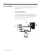
Chapter 4 Configure the Adapter for Direct Connection in RSLogix 5000 Software What This Chapter Contains In this example, a ControlLogix controller communicates with POINT I/O modules via the 1734-AENT adapter using a direct connection. The adapter makes a direct connection to each of the modules referenced by the data. The modules presented in this chapter use RSLogix 5000 software, version 11.
26 Configure the Adapter for Direct Connection in RSLogix 5000 Software We mounted the 1734-AENT adapter on a DIN rail in slot 0, with a 1734-OW2/C relay output module in slot 1, a 1734-OV4E/C sink output module in slot 2, and a power supply (not shown). 1734-AENT 10.88.70.2 POINT I/O Slot 0 1 2 3 Local chassis Data Logix5555 controller (slot 1) Slot 0 1 2 3 4 1756-ENBT 10.88.70.4 (slot 3) Switch 10.88.70.
Configure the Adapter for Direct Connection in RSLogix 5000 Software 27 2. From the File menu, select New. The New Controller dialog opens. 3. Enter an appropriate Name for the Controller, for example, POINT_IO_Controller. 4. Select the correct Version, Chassis Type, and Slot number of the Logix5555 controller, and the folder where you want to save the RSLogix 5000 file (Create In). The Description is optional. RSLogix 5000 software version 11 or later lets you choose to enable redundancy.
28 Configure the Adapter for Direct Connection in RSLogix 5000 Software • Add the local 1756-ENBT module to the I/O configuration. • Add the 1734-AENT adapter as a child of the 1756-ENBT module. • Add the I/O modules as children of the 1734-AENT adapter. IMPORTANT Click the Help buttons on the configuration dialogs shown in this section if you need assistance in selecting and setting the parameters. Add the Local EtherNet/IP Bridge to the I/O Configuration 1.
Configure the Adapter for Direct Connection in RSLogix 5000 Software 29 The Select Module dialog opens. 3. Expand Communications to see the list of Communications modules. 4. Select the 1756-ENBT EtherNet/IP Bridge, and click OK. The Select Major Revision dialog opens. 5. Select the number for Major Revision, and click OK.
30 Configure the Adapter for Direct Connection in RSLogix 5000 Software The New Module dialog opens. 6. Enter values for Name, IP Address, Slot, Electronic Keying, and Revision, noting that we used the following values: Name Local_ENB IP Address 10.88.70.4 Slot 3 Electronic Keying Compatible Keying Revision 3.1 7. Click OK to accept the configuration. The Module Properties dialog opens.
Configure the Adapter for Direct Connection in RSLogix 5000 Software 31 The Select Module dialog opens. 2. Expand Communications to see the list of Communications modules.
32 Configure the Adapter for Direct Connection in RSLogix 5000 Software 3. Select the 1734-AENT/A Ethernet adapter from the list, and click OK, noting that we used these values. Name POINT_IO_Adapter IP Address 10.88.70.2 Comm Format None Chassis Size 3 Electronic Keying Compatible Keying Revision 1.1 The Slot field appears grey because the slot is automatically 0 for the 1734-AENT adapter.
Configure the Adapter for Direct Connection in RSLogix 5000 Software 33 The 1734-AENT adapter appears in the Ethernet folder. Add the POINT I/O Modules to the I/O Configuration You now add POINT I/O modules to the I/O Configuration List under the 1734-AENT adapter. In this example, you add a 1734-OW2 relay output and a 1734-OV4E sink output module with standard configurations. Use these steps as a guide when configuring different I/O modules for your system.
34 Configure the Adapter for Direct Connection in RSLogix 5000 Software The Select Module dialog opens. 2. Expand Digital to see the list of Digital modules. 3. Select the 1734-OW2 relay output module from the list, and click OK. The New Module dialog opens.
Configure the Adapter for Direct Connection in RSLogix 5000 Software 35 4. Enter values for Name and Slot, noting that we used the following values. Name POINT_Relay_Output Slot 1 5. Choose Connection. The RPI is selectable since it is a direct connection. 6. Enter 50 for requested packet interval (RPI) to set how often you exchange data with the 1734-AENT adapter.
36 Configure the Adapter for Direct Connection in RSLogix 5000 Software Add the Digital Output Module 1. Right-click the 1734-AENT adapter, and select New Module. The Select Module dialog opens. 2. Expand Digital to see the list of Digital modules.. 3. Select the 1734-OV4E digital output module from the list. 4. Click OK.
Configure the Adapter for Direct Connection in RSLogix 5000 Software 37 The New Module dialog opens. 5. Enter values for Name and Slot, noting we used the following. Name POINT_Digital_Output Slot 2 6. On the Connection tab, enter 10 ms as the RPI for the 1734-OV4E module. 7. Click OK. The I/O Configuration in the Project dialog should look similar to the following.
38 Configure the Adapter for Direct Connection in RSLogix 5000 Software Edit the Controller Tags When you add modules to the I/O configuration the system creates tags for those modules to use in the application program. For the example application you need to add one more controller tags. 1. Double-click the Controller Tags folder in the project dialog. The Controller Tags dialog opens. You see the tags created for the 1734-AENT adapter and digital I/O modules.
Configure the Adapter for Direct Connection in RSLogix 5000 Software Create the Ladder Program 39 Next create the example ladder program to test the I/O. 1. Double-click Main Routine under the Main Program folder. 2. Enter the following ladder program using the tags previously created. 3. Save the program. Download the Program to the Controller Follow this procedure to download the program you just saved to the ControlLogix controller.
40 Configure the Adapter for Direct Connection in RSLogix 5000 Software 1. From the main menu, choose Communications>Who-Active. The Who Active dialog opens. 2. Navigate to select the slot where the controller is located in the chassis. 3. Choose Set Project Path. 4. Choose Download. The Download dialog opens with a reminder of the following. • The controller is in Remote Run mode. • The mode changes to Remote Program prior to download.
Configure the Adapter for Direct Connection in RSLogix 5000 Software 41 5. From the Download dialog, choose Download to see the RSLogix 5000 software dialog. 6. Notice that the 1756-ENBT Bridge is now online. If yellow triangles are present, see the following section. Verify the Module Chassis Size You have now built the I/O tree in RSLogix 5000 software, and the RSLogix 5000 software used the chassis size from the 1734-AENT General tab.
42 Configure the Adapter for Direct Connection in RSLogix 5000 Software You see the Module Fault error code. 5. Click the Chassis Size tab. 6. Click Set Chassis Size in Module. Value from RSLogix 5000 software Value stored in 1734-AENT adapter 7. Read and acknowledge the warning dialog. 8. Click OK to continue.
Configure the Adapter for Direct Connection in RSLogix 5000 Software 43 Notice the chassis size in the module is modified to 3. 9. Click OK. At this point, your POINTBus status LED should be solid green. All the yellow triangles in your I/O configuration should be gone. Configure the Adapter with Fixed IP Address To configure the 1734-AENT adapter with a fixed IP address to prevent the adapter from ceasing to communicate with the ControlLogix controller: 1.
44 Configure the Adapter for Direct Connection in RSLogix 5000 Software 4. Read and acknowledge the warning. 5. Click OK. 6. Click the Refresh button to verify the changes. Recover From an Overloaded Adapter Each POINT I/O connection established with the 1734-AENT adapter consumes a portion of the microprocessor’s bandwidth.
Chapter 5 Configure the Adapter for Direct Connection and Rack Optimization in RSLogix 5000 Software What This Chapter Contains This chapter guides you through the steps required to configure your POINT I/O Ethernet adapter for both direct connection and rack optimization using RSLogix 5000 software. You can mix communication formats for different I/O modules communicating through the same adapter.
46 Configure the Adapter for Direct Connection and Rack Optimization in RSLogix 5000 Software Set Up the Hardware In this example, a ControlLogix chassis contains the Logix 5555 controller in slot 1 and a 1756-ENBT bridge module in slot 3. We mounted the 1734-AENT adapter on a DIN rail in slot 0, with a 1734-OW2/C relay output module in slot 1, a 1734-OV4E/C sink output module in slot 2, and a power supply (not shown). 1734-AENT 10.88.70.
Configure the Adapter for Direct Connection and Rack Optimization in RSLogix 5000 Software Create the Example Application 47 Perform the following steps to create the example application: 1. Start the RSLogix 5000 Enterprise Series software. You see the RSLogix 5000 main dialog. 2. From the File menu, select New. The New Controller dialog opens. 3. Enter an appropriate Name for the Controller, for example, POINT_IO_Controller. 4. • • • • Specify the following.
48 Configure the Adapter for Direct Connection and Rack Optimization in RSLogix 5000 Software 6. To use redundancy in your system, check the Redundancy Enabled checkbox so that a checkmark appears. RSLogix 5000 software, version 11 and later, includes enable redundancy. This example does not use redundancy. 7. Click OK. Configure the I/O Modules You now add the POINT I/O modules to the controller I/O configuration. To do this, first add the local 1756-ENBT module to the I/O configuration.
Configure the Adapter for Direct Connection and Rack Optimization in RSLogix 5000 Software 49 2. Click New Module. The Select Module dialog opens. 3. Expand Communications to see the list of Communications modules. 4. Select the 1756-ENBT EtherNet/IP Bridge, and click OK. The Select Major Revision dialog opens. 5. Select the value for Major Revision, and click OK.
50 Configure the Adapter for Direct Connection and Rack Optimization in RSLogix 5000 Software The Module Properties dialog opens. 6. Enter values for Name, IP Address, Slot, Electronic Keying, and Revision, noting we used the following values: Name IP Address Slot Electronic Keying Revision Local_ENB 10.88.70.4 3 Compatible Module 1.1 7. Click Finish to accept the configuration.
Configure the Adapter for Direct Connection and Rack Optimization in RSLogix 5000 Software 51 The Select Module dialog opens. 2. Expand Communications to see the list of Communications modules. 3. Select the 1734-AENT/A Ethernet adapter from the list, and click OK. The New Module dialog opens.
52 Configure the Adapter for Direct Connection and Rack Optimization in RSLogix 5000 Software 4. Enter values for Name, IP Address, Comm Format, Chassis Size, Electronic Keying, and Revision, noting we used the following values. Name POINT_IO_Adapter IP Address 10.88.70.2 Comm Format Rack Optimization Chassis Size 4 Electronic Keying Compatible Keying Revision 1.1 The Slot field appears grey because the slot is automatically 0 for the 1734-AENT adapter.
Configure the Adapter for Direct Connection and Rack Optimization in RSLogix 5000 Software 53 7. Verify that the requested packet interval (RPI) is appropriate for your system. You use this value for the rack-optimized connection to the I/O modules. IMPORTANT To avoid overloading the 1734-AENT adapter, we recommend that you set RPI no less than 10 ms for rack connections and 50 ms for direct connections. 8. Click OK. The 1734-AENT adapter appears in the Ethernet folder.
54 Configure the Adapter for Direct Connection and Rack Optimization in RSLogix 5000 Software 2. Expand Digital to see the list of digital modules. 3. Select the 1734-OW2 relay output module from the list, and click OK. The New Module dialog opens. 4. Enter values for Name and Slot. Note that we used the following values. Name Slot 5. Choose Connection.
Configure the Adapter for Direct Connection and Rack Optimization in RSLogix 5000 Software 55 The RPI is selectable, since it is a direct connection. 6. Verify that the requested packet interval (RPI) is appropriate for your system (10 ms for this example). You use this value for the rack-optimized connection to the I/O modules. IMPORTANT To avoid overloading the 1734-AENT adapter, we recommend that the RPI be no less than 10 ms for rack connections and 50 ms for direct connections. 7.
56 Configure the Adapter for Direct Connection and Rack Optimization in RSLogix 5000 Software The Select Module dialog opens. 2. Expand Digital to see the list of digital modules available. 3. Choose the 1734-OV4E/C module, and click OK.
Configure the Adapter for Direct Connection and Rack Optimization in RSLogix 5000 Software 57 The New Module dialog opens. 4. • • • From the New Module dialog, complete the following. Enter a value for Name. Enter a value for Slot. Click Change. The Module Definition dialog opens. 5. From the Connection tab, select Rack Optimization. 6. Click OK. The New Module dialog opens. 7. From the New Module dialog, click the Connection tab.
58 Configure the Adapter for Direct Connection and Rack Optimization in RSLogix 5000 Software The New Module Connection tab dialog opens. 8. On the Connection tab, enter 50 for the requested packet interval (RPI). 9. Keep the following unchecked: • Inhibit Module • Major Fault on Controller If Connection fails While in Run Mode 10. Click OK. 11. Choose File →Save and enter the name and location of the RSLogix 5000 file.
Configure the Adapter for Direct Connection and Rack Optimization in RSLogix 5000 Software 59 3. Choose Set Project Path. 4. Choose Download. You see the Download dialog. 5. From the Download dialog, click Download. You see this RSLogix 5000 dialog. 6. Notice that the 1756-ENBT Bridge is now online. If yellow triangles are present, see the following section.
60 Configure the Adapter for Direct Connection and Rack Optimization in RSLogix 5000 Software 3. Select Properties. 4. Click the Connection tab. You see the Module Fault error code. 5. Click the Chassis Size tab. 6. Click Set Chassis Size in Module.
Configure the Adapter for Direct Connection and Rack Optimization in RSLogix 5000 Software 61 7. Read and acknowledge the warning dialog. 8. Click OK to continue. 9. Notice the chassis size in the module is modified to 3. 10. Click OK. At this point, your POINTBus status LED should be solid green. All the yellow triangles in your I/O configuration tree should be gone. 11. Click OK to close the dialog. 12. Click File →Save to save the project.
62 Configure the Adapter for Direct Connection and Rack Optimization in RSLogix 5000 Software Access Module Data Use the following information to use the 1734 POINT I/O Ethernet adapter data in the ladder logic program. • POINT_IO_Adapter = the name you gave to your Ethernet adapter • # = slot number of POINT I/O module • C = configuration, I = input, O = output This value indicates that slot 2 is the only module participating in the rack-optimized connection with no errors.
Chapter 6 LED Status Indicators What This Chapter Contains Read this chapter for information about LED status indicators. Interpret the Status Indicators Module Status Network Activity Network Status POINTBus Status System Power Field Power 43248aent ATTENTION Indication You must use series C POINT I/O modules with the 1734-AENT adapter. Series A or B POINT I/O modules will not work with this adapter. Probable Cause Recommended Action Off No power applied to device Apply power to the device.
64 LED Status Indicators Indication Probable Cause Recommended Action Network Activity Off No link established. Verify network cabling, and correct, as needed. Flashing green/Off Transmit or receive activity present. None Steady green Link established. None Network Status Off Device not initialized. The module does not have an IP address. Flashing green No CIP connections present. Device has an IP address, but no CIP connections are established.
LED Status Indicators 65 System Power Off Not active; field power is off or DC-DC converter problem present. 1. Verify power is on, and apply power if needed. 2. Verify backplane power not exceeded, and correct. 3. Replace 1734-AENT module. Green System power is on; DC-DC converter is active (5V). None Off Not active; field power is off. Apply field power. Green Power is on; 24V is present.
66 LED Status Indicators Notes: Publication 1734-UM011D-EN-P - May 2011
Appendix A Adapter Web Pages What This Appendix Contains Work with the Home Page Read this appendix for information about the adapter Web page diagnostics that offer extensive internal and network diagnostics. Topic Page Work with the Home Page 67 Work with the Diagnostics Pages 69 Work with the Configuration Pages 76 Work with the Browse Chassis Page 80 Use the adapter diagnostics Home page to access other adapter diagnostics Web pages and see the following information.
68 Adapter Web Pages ATTENTION You must use Series C POINT I/O modules with the 1734-AENT adapter. Series A or B POINT I/O modules will not work with this adapter. 1. From a browser such as Netscape or Microsoft Internet Explorer, enter the adapter IP address to see the Home page. Enter the adapter IP address to see the Home page. 2. From the Home page, click Expand to expand options, as in the figure, or Minimize to see Diagnostics, Configuration, and Browse Chassis options without the expansion.
Adapter Web Pages 69 3. From the Home page, complete one of these, as desired. • Click one of these to go to http://www.ab.com/. – Allen-Bradley logo at the top of the page – Visit ab.com for additional information statement under Resources • Click Rockwell Automation at the top right to go to http://www.rockwellautomation.com/. • Click these to see additional diagnostics Web pages.
70 Adapter Web Pages Use the Diagnostic Overview Page To use the Diagnostic Overview page to view general diagnostics information, follow this procedure. 1. From the Web page, click the Diagnostic Overview tab at the top of the page or panel on the left. The Diagnostic Overview tab opens. 2. From the Diagnostic Overview tab, view the following.
Adapter Web Pages 71 – Open Errors – Conn Closes – Close Errors – Conn Timeout – Status • Module Settings – Chassis Size – Switches Use the Network Settings Page To use the Network Settings page to view network related information, follow this procedure. 1. From the Web page, click the Network Settings tab at the top of the page or panel on the left. The Network Settings tab opens.
72 Adapter Web Pages 2. From the Network Settings page, view the following.
Adapter Web Pages 73 The Ethernet Statistics tab opens. 2.
74 Adapter Web Pages Use the I/O Connections Page To use the I/O Connections page to view CIP I/O (Class 1) connection information, follow this procedure. 1. From the Web page, click the I/O Connections tab at the top of the page or panel on the left. The I/O Connections tab opens. The top value in this column representing Lost shows the number of packets from the source missing. The value for Slot shows the slot number of the I/O module this connection is controlling. 2.
Adapter Web Pages 75 Use the Diagnostic Messaging Page To use the Diagnostic Messaging page to execute explicit, unconnected message services, use this procedure. 1. From the Web page, click the Diagnostic Messaging tab at the top of the page or panel on the left. The Diagnostic Messaging tab opens. 2.
76 Adapter Web Pages 3. From the Diagnostic Messaging tab, click Submit to see values similar to that in the figure. Work with the Configuration Pages To work with the Configuration pages, follow these procedures, noting that values on these pages are stored in and retrieved from non-volatile memory. IMPORTANT The values on these pages are in non-volatile memory. Changes to these parameters do not take effect until you reset or cycle power to the 1734-AENT adapter.
Adapter Web Pages 77 2. From the Configuration page, click one of these. • Identity • Network • Services The Enter Network Password dialog opens. 3. From the user name and password dialog, enter values, noting the following. • The values for user name and password are case sensitive. • The default user name is admin. • The default password is password. 4.
78 Adapter Web Pages You see the Identity page. 2. From the Identity tab, complete entries for the following, noting that the description and location help you identify where modules are in the facility. • Host Name – the name a Domain Name Server uses to resolve this adapter’s IP address • Module Description • Module Location • Chassis Size – the value that shows the number of POINT I/O mdoules plus the adapter.
Adapter Web Pages 79 You see the Network Configuration page. 2. From the Network Configuration tab, complete these entries, noting that values for Network Interface are disabled when DHCP is Dynamic DHCP and port speed and duplex mode are disabled when Autonegotiate Speed and Duplex is selected. • For Initial Network Configuration Ethernet Interface Configuration – Static – Dynamic DHCP • For Network Interface, select from these choices.
80 Adapter Web Pages Use the Services Page To use the Services page to change the password for the Configuration web page or disable the Web server, complete these procedures. 1. From the Web page, click the Services tab at the top of the page or panel on the left. The Services tab opens. 2. From the Services tab, make these entries: • Click in the Enable box to change whether the Web server runs after the module is reset.
Adapter Web Pages 81 To work with the Browse Chassis page, follow these procedures. 1. From the Home page, click Browse Chassis. Check Increase timeout to increase the time of the browse query and time the modules get to respond to the query, which is useful when browsing a busy system. 2. From the Browse Chassis page, leave the Display compact check box unchecked, if desired, unless you want to decrease the font size, making it easier to read the full page after the query. 3.
82 Adapter Web Pages After completion of a query, here is how a typical Browse Chassis page looks with the module hyperlinks active and the Display compact check box unchecked. Click a module hyperlink to view information about the module. Here is how a typical Browse Chassis page looks with the Display compact check box checked. Click a module hyperlink to view information about the module. 5.
Adapter Web Pages 83 • Module Revision • Serial Number • Status Publication 1734-UM011D-EN-P - May 2011
84 Adapter Web Pages Notes: Publication 1734-UM011D-EN-P - May 2011
Appendix B Configure the RSLinx Ethernet Communication Driver What This Appendix Contains To communicate with your 1734-AENT adapter over your network you must configure the RSLinx EtherNet/IP driver (AB_ETH/IP). You need one of these drivers to download the example application programs in this manual.
88 Configure the RSLinx Ethernet Communication Driver Configure the AB_ETH/IP Driver To configure the AB_ETH/IP Ethernet communication driver, perform the following steps. 1. Start RSLinx software. 2. From the Communications menu, select Configure Drivers. 3. Click the arrow to the right of the Available Driver Types box. The Available Driver Types list appears. 4. Select EtherNet/IP Devices and click Add/New. The Configure driver dialog opens.
Configure the RSLinx Ethernet Communication Driver 89 5. Make sure the Browse Local Subnet button is selected. RSLinx software browses your local subnet and automatically reads the IP address. 6. Click OK. The AB_ETH/IP driver is now configured and appears in the configured drivers window. 7. Close RSLinx software.
90 Configure the RSLinx Ethernet Communication Driver Notes: Publication 1734-UM011D-EN-P - May 2011
Appendix C POINT I/O Module and RSLogix 5000 Software Controller Tag Reference What This Appendix Contains Read this appendix for information about tag references. ATTENTION 1734 POINT I/O Catalog Numbers 1734 POINT I/O Catalog Number You must use series C POINT I/O modules with the 1734-AENT adapter. Series A or B POINT I/O modules will not work with this adapter.
92 POINT I/O Module and RSLogix 5000 Software Controller Tag Reference 1734 POINT I/O Catalog Number RSLogix5000 Module Description Specialty I/O 1734-232ASC/C 1 Channel ASCII Interface Module 1734-IJ/C 1 Channel 5V DC Encoder/Counter 1734-IK/C 1 Channel 15…24V DC Encoder/Counter 1734-SSI/C 1 Channel Synchronous Serial Interface 1734-VHSC24/C 1 Channel 15…24V DC Very High-speed Counter 1734-VHSC5/C 1 Channel 5V DC Very High-speed Counter Note that all POINT I/O modules must be series C or ab
POINT I/O Module and RSLogix 5000 Software Controller Tag Reference 93 Digital 2 POINT Input 1734-IA2 2 POINT 120V AC Input 1734-IB2 2 POINT 10…28V DC Input, Sink 1734-IM2 2 POINT 240V AC Input 1734-IV2 2 POINT 10…28V DC Input, Source Configuration Data Data Type Default Value Valid Data Values Filter Off On Time - POINT 0 INT 1,000 -32,768…32,767 µs(1) (0…65,535) Filter On Off Time - POINT 0 INT 1,000 -32,768…32,767 µs (1) (0…65,535) Filter Off On Time - POINT 1 INT 1,000 -32,768…32,767 µs
94 POINT I/O Module and RSLogix 5000 Software Controller Tag Reference Digital 4 POINT Input 1734-IB4 4 POINT 10…28V DC Input, Sink 1734-IV4 4 POINT 10…28V DC Input, Source Configuration Data Data Type Default Value Valid Data Values Filter Off On Time - POINT 0 INT 1,000 -32,768…32,767 µs(1) (0…65,535) Filter On Off Time - POINT 0 INT 1,000 -32,768…32,767 µs(1) (0…65,535) Filter Off On Time - POINT 1 INT 1,000 -32,768…32,767 µs(1) (0…65,535) Filter On Off Time - POINT 1 INT 1,000 -32,7
POINT I/O Module and RSLogix 5000 Software Controller Tag Reference Digital 2 POINT Output – Without Diagnostic Status 95 1734-OA2 2 POINT 120V AC Output 1734-OW2 2 POINT AC/DC Relay Output 1734-OX2 2 POINT Relay Output N.O./N.C.
96 POINT I/O Module and RSLogix 5000 Software Controller Tag Reference Digital 2 POINT Output – With Over Load and Open Load Diagnostic Status Publication 1734-UM011D-EN-P - May 2011 1734-OB2E 2 POINT 10…28V DC Electronically Fused Output, Source 1734-OB2EP 2 POINT 10…28V DC Electronically Fused Protected Output, Source Configuration Data Data Type Default Value Valid Data Values Fault Mode - POINT 0, 1 SINT, BIT 0 0=Fault Value 1=Hold Last State Fault Value - POINT 0, 1 SINT, BIT 0 0=Off 1=O
POINT I/O Module and RSLogix 5000 Software Controller Tag Reference Digital 2 POINT Output – With Over Load Diagnostic Status 97 1734-OV2E 2 POINT 10…28V DC Electronically Fused Output, Sink Configuration Data Data Type Default Value Valid Data Values Fault Mode - POINT 0, 1 SINT, BIT 0 0=Fault Value 1=Hold Last State Fault Value - POINT 0, 1 SINT, BIT 0 0=Off 1=On Program Mode - POINT 0, 1 SINT, BIT 0 0=Program Value 1=Hold Last State Program Value - POINT 0, 1 SINT, BIT 0 0=Off 1=On
98 POINT I/O Module and RSLogix 5000 Software Controller Tag Reference Digital 4 POINT Output – With Over Load and Open Load Diagnostic Status Publication 1734-UM011D-EN-P - May 2011 1734-OB4E 4 POINT 10…28V DC Electronically Fused Output, Source Configuration Data Data Type Default Valid Data Values Value Fault Mode - POINT 0, 1, 2, 3 SINT, BIT 0 0=Fault Value 1=Hold Last State Fault Value - POINT 0, 1, 2, 3 SINT, BIT 0 0=Off 1=On Program Mode - POINT 0, 1, 2, 3 SINT, BIT 0 0=Program Value
POINT I/O Module and RSLogix 5000 Software Controller Tag Reference Digital 4 POINT Output – With Over Load Diagnostic Status 99 1734-OV4E 4 POINT 10…28V DC Electronically Fused Output, Sink Configuration Data Data Type Default Valid Data Values Value Fault Mode - POINT 0, 1, 2, 3 SINT, BIT 0 0=Fault Value 1=Hold Last State Fault Value - POINT 0, 1, 2, 3 SINT, BIT 0 0=Off 1=On Program Mode - POINT 0, 1, 2, 3 SINT, BIT 0 0=Program Value 1=Hold Last State Program Value - POINT 0, 1, 2, 3 SIN
100 POINT I/O Module and RSLogix 5000 Software Controller Tag Reference Analog 2 Channel Input Publication 1734-UM011D-EN-P - May 2011 1734-IE2C 2 Channel Analog Current Input Configuration Data Data Type Default Valid Data Values Value Low Engineering Channel 0 INT 3,277 -32,768…32,767 High Engineering Channel 0 INT 16,383 -32,768…32,767 Digital Filter Channel 0 INT 0 0…10,000 ms Low Alarm Limit Channel 0 INT 3,113 -32,768…32,767 High Alarm Limit Channel 0 INT 16,547 -32,768…32,767
POINT I/O Module and RSLogix 5000 Software Controller Tag Reference 101 1734-IE2C 2 Channel Analog Current Input Input Data Data Type Default Value Valid Data Values Data Channel 0 INT 0 -32,768…32,767 Data Channel 1 INT 0 -32,768…32,767 Status Byte Channel 0 SINT 0 Bit 0 Fault Bit 1 Calibration Bit 2 LowAlarm Bit 3 HighAlarm Bit 4 LowLowAlarm Bit 5 HighHighAlarm Bit 6 Underrange Bit 7 Overrange Status Byte Channel 1 SINT 0 Bit 0 Fault Bit 1 Calibration Bit 2 LowAlarm Bit 3 HighAlarm Bi
102 POINT I/O Module and RSLogix 5000 Software Controller Tag Reference 1734-IE2V 2 Channel Analog Voltage Input Publication 1734-UM011D-EN-P - May 2011 Configuration Data Data Type Default Valid Data Values Value Low Engineering Channel 0 INT 0 -32,768…32,767 High Engineering Channel 0 INT 10,000 -32,768…32,767 Digital Filter Channel 0 INT 0 0…10,000 ms Low Alarm Limit Channel 0 INT 500 -32,768…32,767 High Alarm Limit Channel 0 INT 9,500 -32,768…32,767 Low Low Alarm Limit Channel
POINT I/O Module and RSLogix 5000 Software Controller Tag Reference 103 1734-IE2V 2 Channel Analog Voltage Input Input Data Data Type Default Value Valid Data Values Data Channel 0 INT 0 -32,768…32,767 Data Channel 1 INT 0 -32,768…32,767 Status Byte Channel 0 SINT 0 Bit 0 Fault Bit 1 Calibration Bit 2 LowAlarm Bit 3 HighAlarm Bit 4 LowLowAlarm Bit 5 HighHighAlarm Bit 6 Underrange Bit 7 Overrange Status Byte Channel 1 SINT 0 Bit 0 Fault Bit 1 Calibration Bit 2 LowAlarm Bit 3 HighAlarm Bi
104 POINT I/O Module and RSLogix 5000 Software Controller Tag Reference 1734-IR2 2 Channel RTD Input Publication 1734-UM011D-EN-P - May 2011 Configuration Data Data Type Default Value Valid Data Values Low Engineering Channel 0 INT 1,000 -32,768…32,767 High Engineering Channel 0 INT 5,000 -32,768…32,767 Digital Filter Channel 0 INT 0 0…10,000 ms Low Alarm Limit Channel 0 INT -32,768 -32,768…32,767 High Alarm Limit Channel 0 INT 32,767 -32,768…32,767 Low Low Alarm Limit Channel 0
POINT I/O Module and RSLogix 5000 Software Controller Tag Reference 105 1734-IR2 2 Channel RTD Input Configuration Data Data Type Default Value Valid Data Values Sensor Type Channel 1 SINT 1 0=Ohms 1=100 Ω Pt α 385 2=200 Ω Pt α 385 5=100 Ω JPt α 3916 6=200 Ω JPt α 3916 9=10 Ω Cu α 427 10=120 Ω Ni α 672 11=100 Ω Ni α 618 12=120 Ω Ni α 618 Temperature Mode Channel 1 SINT 1 0=Custom Scale 1=°C 2=°F 3=°K 4=°R Notch Filter (Channel 0 & 1) SINT 1 0=50 Hz 1=60 Hz 2=100 Hz 3=120 Hz 4=200 Hz 5=240 H
106 POINT I/O Module and RSLogix 5000 Software Controller Tag Reference 1734-IT2 2 Channel Thermocouple Input, Isol.
POINT I/O Module and RSLogix 5000 Software Controller Tag Reference 107 1734-IT2 2 Channel Thermocouple Input, Isol. Configuration Data Data Type Default Value Valid Data Values Temperature Mode Channel 0 SINT 1 0=mV/Custom Scale 1=°C 2=°F 3=°K 4=°R Cold Junction Enable Channel 0 SINT 1 0=Disabled 1=Enabled Cold Junction Offset Channel 0 INT 0 0…7,000 (0.00…70.
108 POINT I/O Module and RSLogix 5000 Software Controller Tag Reference 1734-IT2 2 Channel Thermocouple Input, Isol. Configuration Data Data Type Default Value Valid Data Values Temperature Mode Channel 1 SINT 1 0=mV/Custom Scale 1=°C 2=°F 3=°K 4=°R Cold Junction Enable Channel 1 SINT 1 0=Disabled 1=Enabled Cold Junction Offset Channel 1 INT 0 0…7,000 (0.00…70.
POINT I/O Module and RSLogix 5000 Software Controller Tag Reference Analog 2 Channel Output 109 1734-OE2C 2 Channel Analog Current Output Configuration Data Data Type Default Value Valid Data Values Fault Value Channel 0 INT 0 -32,768…32,767 Program Value Channel 0 INT 0 -32,768…32,767 Low Engineering Channel 0 INT 1,638 -32,768…32,767 High Engineering Channel 0 INT 8,191 -32,768…32,767 Low Limit Channel 0 INT -32,768 -32,768…32,767 High Limit Channel 0 INT 32,767 -32,768…32,76
110 POINT I/O Module and RSLogix 5000 Software Controller Tag Reference 1734-OE2C 2 Channel Analog Current Output Publication 1734-UM011D-EN-P - May 2011 Configuration Data Data Type Default Value Valid Data Values Idle Mode Channel 1 SINT 1 0=Hold Last State 1=Go to Low Clamp 2=Go to High Clamp 3=Go to Fault Value Limit Alarm Latch Channel 1 SINT 0 0=No Latching 1=Alarms Latch Alarm Disable Channel 1 SINT 0 0=Alarms Enabled 1=Alarms Disabled Input Data Data Type Default Value Valid D
POINT I/O Module and RSLogix 5000 Software Controller Tag Reference 111 1734-OE2V 2 Channel Analog Voltage Output Configuration Data Data Type Default Value Valid Data Values Fault Value Channel 0 INT 0 -32,768…32,767 Program Value Channel 0 INT 0 -32,768…32,767 Low Engineering Channel 0 INT 0 -32,768…32,767 High Engineering Channel 0 INT 10,000 -32,768…32,767 Low Limit Channel 0 INT -32,768 -32,768…32,767 High Limit Channel 0 INT 32,767 -32,768…32,767 Range Type Channel 0 SIN
112 POINT I/O Module and RSLogix 5000 Software Controller Tag Reference 1734-OE2V 2 Channel Analog Voltage Output Publication 1734-UM011D-EN-P - May 2011 Configuration Data Data Type Default Value Valid Data Values Limit Alarm Latch Channel 1 SINT 0 0=No Latching 1=Alarms Latch Alarm Disable Channel 1 SINT 0 0=Alarms Enabled 1=Alarms Disabled Input Data Data Type Default Value Valid Data Values Status Byte Channel 0 SINT 0 Bit 0 Fault Bit 1 Calibration Bit 2 LowAlarm Bit 3 HighAlarm
POINT I/O Module and RSLogix 5000 Software Controller Tag Reference Specialty I/O 113 1734-VHSC24 1 Channel 15…24V DC Very High-speed Counter 1734-VHSC5 1 Channel 5V DC Very High-speed Counter Configuration Data Data Type Default Value Valid Data Values Counter Config SINT Config_0 Config_1 Config_2 Config_3 BIT 0 BIT 1 BIT 2 BIT 3 0000=0=Counter 0001=1=Encoder X1 0010=2=Encoder X2 0011=3=PWM 0100=4=Encoder X4 0101=5=Period/Rate 0110=6=Continuous/Rate 0111=7=Rate Measurement 1000=8=Pulse Generator
114 POINT I/O Module and RSLogix 5000 Software Controller Tag Reference 1734-VHSC24 1 Channel 15…24V DC Very High-speed Counter 1734-VHSC5 1 Channel 5V DC Very High-speed Counter Configuration Data Data Type Default Value Valid Data Values Scalar SINT 0 Counter Config 5, 6, 8 only: -128…+127 (0…255) Single Bit only: 0, 1, 2, 4, 8, 16, 32, 64, -128 Output Ties 0 Out 0 Window 1 Out 0 Window 2 Out 0 Window 3 Out 0 Window 4 SINT BIT 0 BIT 1 BIT 2 BIT 3 0 Output Ties 1 Out 1 Window 1 Out 1 Window 2 O
POINT I/O Module and RSLogix 5000 Software Controller Tag Reference 115 1734-VHSC24 1 Channel 15…24V DC Very High-speed Counter 1734-VHSC5 1 Channel 5V DC Very High-speed Counter Configuration Data Data Type Default Value SS Output Control SINT Valid Data Values 0 SS Out 0 Force BIT 0 0=Output Off 1=Output Forced On SS Out 0 En BIT 1 0=Output Disabled 1=Output Enabled SS Out 0 Electronic Fuse BIT 2 0=Auto Retry 1=Latch Off SS Out 0 Diagnostic Speed BIT 3 0 < 8 ms Response 1=50 ms Response
116 POINT I/O Module and RSLogix 5000 Software Controller Tag Reference 1734-VHSC24 1 Channel 15…24V DC Very High-speed Counter 1734-VHSC5 1 Channel 5V DC Very High-speed Counter Input Data Data Type Default Value Valid Data Values Present Data DINT 0 0…16,777,215 Stored Data DINT 0 -2,147,483,648…2,147,483,64 7 (0…4,294,967,295) Status INT 0 Zero Frequency Detected BIT 1 0=No Fault 1=Fault Detected Stored Data Count_2 Stored Data Count_3 BIT 2 BIT 3 Cycles through 0, 1, 2, 3, 0, Incre
POINT I/O Module and RSLogix 5000 Software Controller Tag Reference 117 Stored Data To interpret values from -2,147,483,648 to -1, use this conversion formula: Stored Data Tag Value + 4,294,967,296 = Actual Stored Data Tag Value.
118 POINT I/O Module and RSLogix 5000 Software Controller Tag Reference 1734-VHSC24 1 Channel 15…24V DC Very High-speed Counter 1734-VHSC5 1 Channel 5V DC Very High-speed Counter Output Data Data Type Default Value Valid Data Values PWM Value INT 0 0…9500 (0.00…95.
POINT I/O Module and RSLogix 5000 Software Controller Tag Reference 119 1734-IJ 1 Channel 5V DC Encoder / Counter 1734-IK 1 Channel 15…24V DC Encoder / Counter Configuration Data Data Type Default Value Counter Config Config_0 Config_1 Config_2 Config_3 SINT BIT 0 BIT 1 BIT 2 BIT 3 0 Valid Data Values 0000=0=Counter 0001=1=Encoder X1 0010=2=Encoder X2 0100=4=Encoder X4 0101=5=Period/Rate 0111=7=Rate Measurement Mode_4 Mode_5 Mode_6 BIT 4 BIT 5 BIT 6 000=Store Count Disable 001=Store/Continue 010
120 POINT I/O Module and RSLogix 5000 Software Controller Tag Reference 1734-IJ 1 Channel 5V DC Encoder / Counter 1734-IK 1 Channel 15…24V DC Encoder / Counter Configuration Data Data Type Default Value Valid Data Values SS Counter Control SS Counter Reset SINT BIT 0 0 SS Counter Preset BIT 1 0=Count Unchanged 1=Count Set to Preset SS Value Reset BIT 2 0=Count Unchanged 1=Count Cleared 0=Count Unchanged 1=Count Cleared To enter values from +128…+255, use these conversion formulas: Decimal P
POINT I/O Module and RSLogix 5000 Software Controller Tag Reference 121 1734-IJ 1 Channel 5V DC Encoder / Counter 1734-IK 1 Channel 15…24V DC Encoder / Counter Input Data Data Type Default Value Valid Data Values Present Data DINT 0 0…16,777,215 Stored Data DINT 0 -2,147,483,648… 2,147,483,647 (0…4,294,967,295) Status Zero Frequency Detected INT BIT 1 0 0=No Fault 1=Fault Detected Stored Data Count_2 BIT 2 Cycles through 0, 1, 2, 3, 0, Stored Data Count_3 BIT 3 Increments after update
122 POINT I/O Module and RSLogix 5000 Software Controller Tag Reference Program Fault Note Programming Fault Error bit – If an incomplete, incorrect, or conflicting set of configuration parameters is sent to the module, the Program Fault bit is asserted and an error code placed in the Programming Error Code word (assembly 6816). The module will not enter a normal operational state.
POINT I/O Module and RSLogix 5000 Software Controller Tag Reference 123 1734-SSI 1 Channel Synchronous Serial Interface Configuration Data Data Type Default Value Valid Data Values Run SINT 1 0=Module Not Running 1=Module Is Running Gray Binary SINT 1 0=Binary Code 1=Gray Code Word Length SINT 13 2…31 Data Speed SINT 5 5=125 Kbps 6=250 Kbps 7=500 Kbps 8=1 MB 9=2 MB G2B Convert (Gray to Binary) SINT 0 0=No Convert 1=Convert Standardization (Divide / Shift using Trailing) SINT 0 0
124 POINT I/O Module and RSLogix 5000 Software Controller Tag Reference SSI Word Delay Time To enter Delay values from +32,768…+65,535 µs, use this conversion formula: Desired Delay Value (in µs) - 65536 = Entered Delay Value (in µs). As an example, for a 40 ms delay time, 40000 - 65536 = -25536 Sensor Resolution To enter Resolution values from +32,768…+65,535 µs, use this conversion formula: Desired Resolution Value - 65536 = Entered Resolution Value.
POINT I/O Module and RSLogix 5000 Software Controller Tag Reference 125 1734-SSI 1 Channel Synchronous Serial Interface Input Data Data Type Default Value Valid Data Values Present Data DINT 0 -2,147,483,648…2,147,483,647 (0…4,294,967,295) Latched Data DINT 0 -2,147,483,648…2,147,483,647 (0…4,294,967,295) Status Input Status INT BIT 0 0 Run BIT 1 0=Module is not Running 1=Module is Running Decreasing Count BIT 2 0=Count not Decreasing 1=Count is Decreasing Increasing Count BIT 3 0=C
126 POINT I/O Module and RSLogix 5000 Software Controller Tag Reference 1734-SSI 1 Channel Synchronous Serial Interface Publication 1734-UM011D-EN-P - May 2011 Output Data Data Type Default Value Valid Data Values Control SINT 0 Latch Acknowledge BIT 0 0 0=Latch Not Cleared 1=Latch Cleared Compare 0 Acknowledge BIT 1 0 0=Compare0 Not Reset 1=Compare0 Reset Compare 1 Acknowledge BIT 2 0 0=Compare1 Not Reset 1=Compare1 Reset Compare 0 Select BIT 3 0 0=Compare0 Not Selected 1=Compare0
POINT I/O Module and RSLogix 5000 Software Controller Tag Reference 127 1734-232ASC 1 Channel ASCII Interface Module Configuration Data Data Type Default Value Valid Data Values Serial Character Format (ASCII Format: Data Bits / Parity / Stop) SINT 0 0=7N2 1=7E1 2=7O1 3=8N1 4=8N2 5=8E1 6=8O1 7=7E2 8=7O2 Serial Comm Speed SINT (Communication Rate of the Serial Port) 0 0=9600 Kbps 1=1200 Kbps 2=2400 Kbps 3=4800 Kbps 4=19.2 KBps 5=38.
128 POINT I/O Module and RSLogix 5000 Software Controller Tag Reference 1734-232ASC 1 Channel ASCII Interface Module Configuration Data Data Type Default Value Valid Data Values Transmit End Delimiter Mode SINT 2 0=No End Delimiter 1=Exclude End Delimiter 2=Include End Delimiter Transmit End Delimiter Character SINT 13 (0x0d) Any Valid ASCII Character (Default is Carr.
POINT I/O Module and RSLogix 5000 Software Controller Tag Reference 129 1734-232ASC 1 Channel ASCII Interface Module Input Data Data Type Default Value Valid Data Values Receive Record Number SINT 0 -128…+127 (0…255) Status TX FIFO Overflow SINT BIT 0 0 RX FIFO Overflow BIT 1 0=No Error 1=RX FIFO Overflow Error RX Parity Error BIT 2 0=No Error 1=RX Parity Overflow Error Handshake Error BIT 6 0=No Error 1=Handshake Error New Data Flag BIT 7 0=No New Data 1=New Data Present Length_Lo
130 POINT I/O Module and RSLogix 5000 Software Controller Tag Reference Transmit Record Number/ Receive Record Number / Length_Lo Note that 7 data bits allows Transmit / Receive record Number of Length_Lo values of 0…127, which RSLogix 5000 software does support in the signed Short Integer data type SINT (-128…+127 range). Note that 8 data bits allows Transmit / Receive record Number of Length_Lo values of 0…255.
Appendix D Quick Start What This Appendix Contains In this quick start, you learn how to use the 1734-AENT adapter with a ControlLogix controller for EtherNet/IP systems. IMPORTANT ATTENTION This quick start contains a simple set of steps and reminders that will help you avoid errors when you are configuring your POINT I/O system for and EtherNet/IP network. You must use series C POINT I/O modules with the 1734-AENT adapter. Series A or B POINT I/O modules will not work with this adapter.
132 Quick Start Configure the Adapter In the 1734-AENT Module Properties dialog, perform the following steps. 1. Complete the Name field. 2. Enter the following address into the IP Address field: 192.168.1.42 You are setting the last digit, because the first three digits are set for you as set by the push wheel switches on the adapter. The push wheel switches should be set to 042. 3.
Quick Start 133 Enter Adapter Properties Use this procedure to enter adapter properties. 1. Right-click the 1734-AENT adapter and select Properties. The Module Properties dialog appears. 2. Click the Chassis Size tab. Notice that the data under this tab is dimmed while offline. Use the Chassis Size tab to send the module size from the General tab to the module itself once you are online. Otherwise, you get an error. We explore this later. For now, click OK to close this dialog: 3.
134 Quick Start 5. In the Module Properties dialog, enter the following information. a. Name b. Slot c. Comm Format d. Electronic Keying, choose Compatible Module to verify the major revision C, because only series C modules support EtherNet/IP. e. Click Next on the bottom of the dialog. f. Set the RPI to 10 ms for digital and 50 ms for analog or specialty. 6. Click Finish. Add Another Module Under the Adapter Use this procedure to add another module under the adapter. 1.
Quick Start Configure 1734 POINT I/O Modules 135 For RSLogix 5000 software version 13 and earlier, configure your POINT I/O modules via the Controller Tags database, using the following steps. For RSLogix 5000 software, versions 15 or later, the preferred method for module configuration is to use the Module Properties dialog for each POINT I/O module, as described in the individual user manual for the module. 1. Double-click the Controller Tags in the project dialog.
136 Quick Start • 2 = 0…10V DC • 0 = -10…+10V DC 5. Click the value 2 and change it to 0, which changes the voltage range to -10…+10V DC for channel 0. Note the following: • The controller sends the configuration data only when connection is being established. • Should you need to modify any of the tag values once you change the tag, you need to access the updated information and download it into the module. These are the ways to download the updated configuration information into the module.
Quick Start 137 – If you downloaded the offline configuration into the module and then realize that you must modify any of the module’s configuration parameters, then the preferred way to make these changes online is to go to the Module Connection tab and inhibit the module, apply the changes, and then uninhibit the module. Doing this breaks the connection, causing the configuration information to be downloaded right after the connection is made.
138 Quick Start Now you can put your controller in Run mode, and the connection should be successful. IMPORTANT Configure an Ethernet Driver in RSLinx Software The information found in the Controller Tag Reference section of this user manual is also available in the RSLogix 5000 online help file. Use the Help file search function under the 1734 catalog number that you are configuring and select the Module Defined Data Types option. You see all of the configurable parameters and associated values.
Quick Start 139 The Rockwell Software RSLinx Gateway - [RSWho - 1] screen appears. TIP The RSWho screen is actually RSLinx’s network browser interface, which lets you view all of your active network connections. The left pane of this display is the Tree Control, which shows networks and devices in a hierarchical view. When a network or device is collapsed, as indicated by the + sign, you can click the + sign or double-click the network or device icon to expand the view and begin browsing.
140 Quick Start Add the AB_ETHIP-1 (EtherNet/IP) Driver 1. From the Communications menu, choose Configure Drivers. The Configure Drivers dialog appears. 2. From the Available Driver Types pull-down menu, choose EtherNet/IP Driver. 3. Click the Add New button. 4. Click OK to accept the default name (AB_ETHIP-1). Be sure that the radio button for Browse Local Subnet is enabled. 5. Click OK. 6.
Index Numerics 1734-POINT I/O catalog numbers 89 A AB-ETHIP driver 85 access module data 62 adapter features 4 replacing on system 11 wiring 12 auto negotiate 16 autobaud 8 B bandwidth, insufficient 44 BootP/DHCP utility 20 browse chassis page 80 disabled web server function 16 E edit controller tags 38 empty slots 2 empty terminal bases 3 example applications v F firmware revisions 5, 8 fixed IP address 43 G gateway address 17 H hardware 25, 46 C catalog numbers 89 chassis size 1 CIP Common Industr
142 Index P power up system for the first time 4 producer/consumer model understanding 6 program fault note 115, 120 publications related vi Q quick start 129 R rack optimized connection 7 recover from an overloaded adapter 44 reinsertion of modules 2 relation list 22 removal of modules 2 replace adapter on system 11 replacement of adapter 2 requested packet interval (RPI) 6 RIUP remove and replace under power 2 Rockwell BootP/DHCP utility 20 RPI requested packet interval 6 RSLinx Ethernet communication
Rockwell Automation Support Rockwell Automation provides technical information on the Web to assist you in using its products. At http://www.rockwellautomation.com/support/, you can find technical manuals, a knowledge base of FAQs, technical and application notes, sample code and links to software service packs, and a MySupport feature that you can customize to make the best use of these tools.