
User manual


Publication 1734-UM011D-EN-P - May 2011
26 Configure the Adapter for Direct Connection in RSLogix 5000 Software
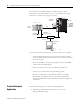
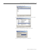
We mounted the 1734-AENT adapter on a DIN rail in slot 0, with a
1734-OW2/C relay output module in slot 1, a 1734-OV4E/C sink output
module in slot 2, and a power supply (not shown).
To work along with this example, set up your system as shown in the figure.
• In the example application, we assume that the Logix5555 controller
and 1756-ENBT module (firmware revision 2.3, or later) are in the slots
shown in the figure.
• Verify the IP addresses for your programming terminal, 1756-ENBT
module, and 1734-AENT adapter.
• Verify the position (slot) of the I/O modules on the DIN rail.
• Verify that you connected all wiring and cabling properly.
• Be sure you configured your communication driver (for example,
AB_ETH/IP-1) in RSLinx software, as described in Appendix A
Configure the RSLinx Ethernet Communication Driver on page 87 of
this manual.
Create the Example
Application
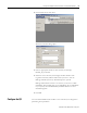
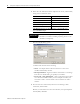
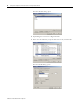
Perform the following steps to create the example application:
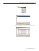
1. Start RSLogix 5000 Enterprise Series software to open the
RSLogix 5000 Main dialog.
Local
chassis
POINT I/O
Logix5555
controller (slot 1)
1756-ENBT
10.88.70.4 (slot 3)
Data
Switch
10.88.70.26
Programming
terminal
Slot 0 1 2 3
1734-AENT
10.88.70.2
Slot 0 1 2 3 4
31393-M