GuardLogix Controller Systems Catalog Numbers 1756-L61S, 1756-L62S, 1756-L63S, 1768-L43S, 1768-L45S Safety Reference Manual
Important User Information Solid state equipment has operational characteristics differing from those of electromechanical equipment. Safety Guidelines for the Application, Installation and Maintenance of Solid State Controls (publication SGI-1.1 available from your local Rockwell Automation sales office or online at http://www.rockwellautomation.com/literature/) describes some important differences between solid state equipment and hard-wired electromechanical devices.
Summary of Changes The information below summarizes the changes to this manual since the last publication. To help you find new and updated information in this release of the manual, we have included change bars as shown to the right of this paragraph. This manual now covers 1768 Compact GuardLogix controllers as well as 1756 GuardLogix controllers. When ‘GuardLogix’ is used alone throughout the manual, it refers to both 1756 and 1768 GuardLogix controllers.
Summary of Changes 4 Publication 1756-RM093F-EN-P - January 2010
Table of Contents Preface Introduction . . . . . . . . . . . . . . . . About This Publication . . . . . . . . Who Should Use This Publication Understanding Terminology . . . . Additional Resources. . . . . . . . . . . . . . . . . . . . . . . . . . . . . . . . . . . . . . . . . . . . . . . . . . . . . . . . . . . . . . . . . . . . . . . . . . . . . . . . . . . . . . . . . . . . . . . . . . . . . . . . . . . . . . . 9 . 9 . 9 10 11 Introduction . . . . . . . . . . . . . . . . . . . . . .
Table of Contents Safety Considerations for CIP Safety I/O Modules . Ownership . . . . . . . . . . . . . . . . . . . . . . . . . . Safety I/O Configuration Signature . . . . . . . . . I/O Module Replacement . . . . . . . . . . . . . . . . . . . . . . . . . . . . . . . . . . . . . . . . . . . . . . . . 31 31 31 32 Chapter 4 CIP Safety and the Safety Network Introduction . . . . . . . . . . . . . . . . . . . . . . . . . . . . . . . . . . . . 35 The Routable CIP Safety Control System. . . . . . . .
Table of Contents Create the Project. . . . . . . . . . . . . . . . . . . . . . . . . . . Test the Application Program . . . . . . . . . . . . . . . . . . Generate the Safety Task Signature . . . . . . . . . . . . . . Project Verification Test . . . . . . . . . . . . . . . . . . . . . . Confirm the Project . . . . . . . . . . . . . . . . . . . . . . . . . Safety Validation . . . . . . . . . . . . . . . . . . . . . . . . . . . Lock the GuardLogix Controller . . . . . . . . . . . . . . . .
Table of Contents Create a Safety Add-On Instruction . . . . . . . . . . . . . . Generate Instruction Signature . . . . . . . . . . . . . . . . . Download and Generate Safety Instruction Signature. SIL 3 Add-On Instruction Qualification Test. . . . . . . . Confirm the Project . . . . . . . . . . . . . . . . . . . . . . . . . Safety Validate Add-On Instructions . . . . . . . . . . . . . Create Signature History Entry . . . . . . . . . . . . . . . . . Export and Import the Safety Add-On Instruction . . .
Preface Introduction Topic About This Publication Page About This Publication 9 Who Should Use This Publication 9 Understanding Terminology 10 Additional Resources 11 This manual is intended to describe the GuardLogix controller system, which is type-approved and certified for use in safety applications up to and including SIL 3 according to IEC 61508 and IEC 62061, safety applications up to and including Performance Level PLe (Category 4) according to ISO 13849-1.
Preface Understanding Terminology The following table defines terms used in this manual. Terms and Definitions Abbreviation Full Term Definition 1oo2 One out of Two Identifies the programmable electronic controller architecture. CIP Common Industrial Protocol A communication protocol designed for industrial automation applications.
Preface Additional Resources The table below provides a listing of publications that contain important information about GuardLogix controller systems.
Preface Notes: 12 Publication 1756-RM093F-EN-P - January 2010
Chapter 1 Safety Integrity Level (SIL) Concept Introduction This chapter introduces you to the Safety Integrity Level (SIL) concept and how the GuardLogix controller meets the requirements for SIL 3 certification.
Chapter 1 Safety Integrity Level (SIL) Concept The TÜV Rheinland has approved GuardLogix controller systems for use in safety-related applications up to SIL 3, in which the de-energized state is considered to be the safe state. All of the examples related to I/O included in this manual are based on achieving de-energization as the safe state for typical Machine Safety and Emergency Shutdown (ESD) Systems.
Safety Integrity Level (SIL) Concept GuardLogix Architecture for SIL 3 Applications Chapter 1 The following illustration shows a typical SIL function, including: • the overall safety function. • the GuardLogix portion of the overall safety function. • how other devices (for example, HMI) are connected, while operating outside the function.
Chapter 1 Safety Integrity Level (SIL) Concept GuardLogix System Components The tables in this section list SIL 3-certified GuardLogix components for both 1756 and 1768 systems as well as non-SIL 3-certified components that may be used with SIL 3 GuardLogix systems. For the most current list of GuardLogix controller and CIP Safety I/O modules certified series and firmware revisions, see http://www.rockwellautomation.com/products/certification/safety/. Firmware revisions are available at http://support.
Safety Integrity Level (SIL) Concept Chapter 1 Components Suitable for Use With 1756 GuardLogix Controller Safety Systems Related Documentation(4) Device Type Chassis Power supply Communication modules Cat. No.
Safety Integrity Level (SIL) Concept IEC62061 IEC 61511 IEC 61508 (SIL 3) UL 1998 UL 508 Catalog Number ISO 13849-1:2006 (PLe) This table lists the main GuardLogix certifications. For the full listing of current safety certifications and associated products, refer to http://www.rockwellautomation.com/products/certification/safety/ index.html. NFPA 79 GuardLogix Certifications ANSI RIA 15.
Safety Integrity Level (SIL) Concept GuardLogix PFD and PFH Specifications Chapter 1 Safety-related systems can be classified as operating in either a low demand mode, or in a high demand/continuous mode. IEC 61508 quantifies this classification by stating that the frequency of demands for operation of the safety system is no greater than once per year in the low demand mode, or greater than once per year in high demand/continuous mode.
Chapter 1 Safety Integrity Level (SIL) Concept To determine the logic element PFH for each safety loop in the simple example system shown in the PFH Example, sum the PFH values for each component in the loop. The PFH Equations by Safety Loop table provides a simplified example of PFH value calculations for each safety loop shown in the PFH Example illustration.
Safety Integrity Level (SIL) Concept System Reaction Time Chapter 1 The system reaction time is the amount of time from a safety-related event as an input to the system until the system sets corresponding outputs to their safe state. Faults within the system can also have an effect upon the reaction time of the system. The system reaction time is the sum of the following reaction times.
Chapter 1 Safety Integrity Level (SIL) Concept Contact Information If Device Failure Occurs If you experience a failure with any SIL 3-certified device, contact your local Rockwell Automation distributor. With this contact, you can: • return the device to Rockwell Automation so the failure is appropriately logged for the catalog number affected and a record is made of the failure. • request a failure analysis (if necessary) to try to determine the cause of the failure.
Chapter 2 GuardLogix Controller System Introduction Topic Page 1756 GuardLogix Controller Hardware 23 1768 Compact GuardLogix Controller Hardware 25 CIP Safety Protocol 25 Safety I/O 25 Communication Bridges 26 Programming Overview 28 For a brief listing of components suitable for use in Safety Integrity Level (SIL) 3 applications, see the table on page 16. For more detailed and up-to-date information see http://www.rockwellautomation.com/products/certification/safety/.
Chapter 2 GuardLogix Controller System Primary Controller The primary controller is the processor that performs standard and safety control functions and communicates with the safety partner for safety-related functions in the GuardLogix control system. The primary controller consists of a central processor, I/O interface, and memory. Safety Partner To satisfy SIL 3 requirements, a safety partner, catalog number 1756-LSP, must be installed in the slot immediately to the right of the primary controller.
GuardLogix Controller System Chapter 2 No extra configuration or wiring is required for SIL 3 operation of the ControlLogix power supplies. Any failure would be detected as a failure by one or more of the active components of the GuardLogix system. Therefore, the power supply is not relevant to the safety discussion.
Chapter 2 GuardLogix Controller System Communication Bridges These communication interface modules are available to facilitate communication over Ethernet/IP, DeviceNet, and ControlNet networks via the CIP Safety protocol.
GuardLogix Controller System Chapter 2 Peer-to-peer safety communication between two 1756 GuardLogix controllers in the same chassis is also possible via the backplane. TIP 1756-LSP 1756-L62S 1756-LSP 1756-L62S Backplane DeviceNet Safety Network The 1756-DNB DeviceNet bridge module lets the 1756 GuardLogix controller control and exchange safety data with CIP Safety I/O modules on a DeviceNet network.
Chapter 2 GuardLogix Controller System Programming Overview The programming software for the GuardLogix controller is RSLogix 5000 software. RSLogix 5000 software is used to define the location, ownership, and configuration of I/O modules and controllers. The software is also used to create, test, and debug application logic. Initially, only relay ladder logic is supported in the GuardLogix safety task. See Appendix A for information on the set of logic instructions available for safety applications.
Chapter 3 CIP Safety I/O for the GuardLogix Control System Introduction Topic Overview Page Overview 29 Typical Safety Functions of CIP Safety I/O Modules 29 Reaction Time 31 Safety Considerations for CIP Safety I/O Modules 31 Before operating a GuardLogix safety system containing CIP Safety I/O modules, you must read, understand, and follow the installation, operation, and safety information provided in the publications listed in the SIL 3-Certified GuardLogix Components tables on page 16.
Chapter 3 CIP Safety I/O for the GuardLogix Control System Diagnostics CIP Safety I/O modules perform self-diagnostics when the power is turned ON and periodically during operation. If a diagnostic failure is detected, safety input data (to the controller) and local safety outputs are set to their safe state (OFF). Status Data In addition to safety input and output data, CIP Safety I/O modules support status data to monitor module and I/O circuit health.
CIP Safety I/O for the GuardLogix Control System Reaction Time Chapter 3 The input reaction time is the time from when the signal changes on an input terminal to when safety data is sent to the GuardLogix controller. The output reaction time is the time from when safety data is received from the GuardLogix controller to when the output terminal changes state. For information on determining the input and output reaction times, refer to the product documentation for your specific CIP Safety I/O module.
Chapter 3 CIP Safety I/O for the GuardLogix Control System I/O Module Replacement The replacement of safety devices requires that the replacement device be configured properly and that the replacement device’s operation be user-verified. ATTENTION During replacement or functional testing of a module, the safety of the system must not rely on any portion of the affected module.
CIP Safety I/O for the GuardLogix Control System Chapter 3 Configure Only When No Safety Signature Exists This setting instructs the GuardLogix controller to configure a safety module only when the safety task does not have a safety task signature, and the replacement module is in an out-of-box condition, meaning that a safety network number does not exist in the safety module.
Chapter 3 CIP Safety I/O for the GuardLogix Control System Notes: 34 Publication 1756-RM093F-EN-P - January 2010
Chapter 4 CIP Safety and the Safety Network Number Introduction To understand the safety requirements of a CIP Safety control system, including the safety network number (SNN), you must first understand how communication is routable in CIP control systems. Topic The Routable CIP Safety Control System Page The Routable CIP Safety Control System 35 Considerations for Assigning the Safety Network Number (SNN) 38 The CIP Safety control system represents a set of interconnected CIP Safety devices.
Chapter 4 CIP Safety and the Safety Network Number Unique Node Reference The CIP Safety protocol is an end-node to end-node safety protocol. The CIP Safety protocol allows the routing of CIP Safety messages to and from CIP Safety devices through non-certified bridges, switches, and routers. To prevent errors in non-certified bridges, switches, or routers from becoming dangerous, each end node within a routable CIP Safety control system must have a unique node reference.
CIP Safety and the Safety Network Number Chapter 4 Each CIP Safety device must be configured with an SNN. Any device that originates a safety connection to another safety device must be configured with the SNN of the target device. If the CIP Safety system is in the start-up process prior to the functional safety testing of the system, the originating device may be used to set the unique node reference into the device. The SNN used by the system is a 6-byte hexadecimal number.
Chapter 4 CIP Safety and the Safety Network Number Considerations for Assigning the Safety Network Number (SNN) The assignment of the SNN is dependent upon factors including the configuration of the controller or CIP Safety I/O module. Safety Network Number (SNN) for Safety Consumed Tags When a safety controller that contains produced safety tags is added to the I/O Configuration tree, the SNN of the producing controller must be entered.
CIP Safety and the Safety Network Number Chapter 4 Refer to the GuardLogix Controllers User Manual, publication 1756-UM020, or the 1768 Compact GuardLogix Controllers User Manual, publication 1768-UM002, for information on changing, copying, and pasting safety network numbers.
Chapter 4 CIP Safety and the Safety Network Number Notes: 40 Publication 1756-RM093F-EN-P - January 2010
Chapter 5 Characteristics of Safety Tags, the Safety Task, and Safety Programs Introduction This chapter explains how to use the standard and safety components of the GuardLogix system.
Chapter 5 Characteristics of Safety Tags, the Safety Task, and Safety Programs SIL 2 Safety Applications You can perform SIL 2 safety control by using the 1756 or 1768 GuardLogix controller’s safety task. Because 1756 GuardLogix controllers are part of the ControlLogix series of processors, you can perform SIL 2 safety control with a 1756 GuardLogix controller by using standard tasks or the safety task.
Characteristics of Safety Tags, the Safety Task, and Safety Programs Chapter 5 Safety-locking the safety task once testing is completed is recommended for SIL 2 applications. Locking the safety task enables additional security features. You may also use FactoryTalk Security and RSLogix 5000 routine source protection to limit access to safety-related logic.
Chapter 5 Characteristics of Safety Tags, the Safety Task, and Safety Programs For Cat 1, Cat 2, and SIL 2 safety functions, the Guard I/O safety modules need specific configurations within the GuardLogix project. In this example, inputs 0, 1, 6, 7, 8, 9, 10, and 11 are part of a CAT 1, 2 or SIL 2 safety function. Inputs 2 and 3, as well as 4 and 5 are part of a CAT 3, CAT 4, or SIL 3 safety function.
Characteristics of Safety Tags, the Safety Task, and Safety Programs Chapter 5 SIL 2 Safety Control in Standard Tasks (1756 GuardLogix Controllers Only) Because of the quality and amount of diagnostics built into the 1756 ControlLogix series of controllers, you can perform SIL 2 safety functions from within standard tasks. This is also true for 1756 GuardLogix controllers.
Chapter 5 Characteristics of Safety Tags, the Safety Task, and Safety Programs SIL 2 Input Data Keep channel A and channel B input data separate at all times. This example illustrates one method for separating channel A and channel B data in your application. Any logic processing that needs to occur must follow ControlLogix SIL 2 guidelines. IMPORTANT Do not perform safety-specific functions within these routines. Safety evaluation must be handled within the 1756 GuardLogix safety task.
Characteristics of Safety Tags, the Safety Task, and Safety Programs Chapter 5 SIL 2 Outputs Follow these guidelines for SIL 2 outputs: • Guard I/O output modules used for SIL 2 safety outputs must be configured for dual-channel operation. • All Guard I/O output modules are approved for use in SIL 2 applications.
Chapter 5 Characteristics of Safety Tags, the Safety Task, and Safety Programs Safety Task Limitations You specify both the safety task period and the safety task watchdog. The safety task period is the period at which the safety task executes. The safety task watchdog is the maximum time allowed from the start of safety task scheduled execution to its completion. For more information on the safety task watchdog, see Appendix C, Reaction Times.
Characteristics of Safety Tags, the Safety Task, and Safety Programs Chapter 5 • Safety input values are frozen at the start of safety task execution. As a result, timer-related instructions, such as TON and TOF, will not update during a single safety task execution. They will keep accurate time from one task execution to another, but the accumulated time will not change during safety task execution.
Chapter 5 Characteristics of Safety Tags, the Safety Task, and Safety Programs Safety Routines Safety routines have all the attributes of standard routines, except that they can exist only in safety programs. One safety routine may be designated as the main routine. Another safety routine may be designated as the fault routine. Only safety-certified instructions may be used in safety routines. For a listing of safety instructions, see Appendix A.
Characteristics of Safety Tags, the Safety Task, and Safety Programs Chapter 5 Tags classified as safety tags are either controller-scoped or program-scoped. Controller-scoped safety tags can be read by either standard or safety logic or other communication devices, but can only be written to by safety logic or another GuardLogix safety controller. Program-scoped safety tags are only accessible by local safety routines. These are routines that reside within the safety program.
Chapter 5 Characteristics of Safety Tags, the Safety Task, and Safety Programs Additional Resources 52 Resource Description Logix5000 Controllers Design Considerations Reference Manual, publication 1756-RM094 Provides information on managing tasks and the effects of task execution and timing on user data GuardLogix Controllers User Manual, publication 1756-UM020 Contains information on how to map tags 1768 Compact GuardLogix Controllers User Manual, publication 1768-UM002 Contains information on
Chapter 6 Safety Application Development Introduction Topic Page Safety Concept Assumptions 53 Basics of Application Development and Testing 53 Commissioning Life Cycle 54 Downloading the Safety Application Program 61 Uploading the Safety Application Program 61 Online Editing 61 Storing and Loading a Project from Nonvolatile Memory 62 Force Data 62 Inhibit a Module 63 Editing Your Safety Application 63 Safety Concept Assumptions The safety concept assumes that: Basics of Applicat
Chapter 6 Safety Application Development Commissioning Life Cycle The flowchart below shows the steps required for commissioning a GuardLogix system. The items in bold text are explained in the following sections.
Safety Application Development Chapter 6 Specification of the Control Function You must create a specification for your control function. Use this specification to verify that program logic correctly and fully addresses your application’s functional and safety control requirements. The specification may be presented in a variety of formats, depending on your application. However, the specification must be a detailed description that includes (if applicable): • • • • • • sequence of operations.
Chapter 6 Safety Application Development Create the Project The logic and instructions used in programming the application must be: • • • • easy easy easy easy to to to to understand. trace. change. test. All logic should be reviewed and tested. Keep safety-related logic and standard logic separate.
Safety Application Development Chapter 6 Generate the Safety Task Signature The safety task signature uniquely identifies each project, including its logic, data, and tags. The safety task signature is composed of an ID (identification number), date, and time. You can generate the safety task signature if all of the following conditions are true: • • • • RSLogix 5000 software is online with the controller. The controller is in program mode. The controller is safety-unlocked.
Chapter 6 Safety Application Development You must include a set of tests to prove the validity of the calculations (formulas) used in your application logic. Equivalent range tests are acceptable. These are tests within the defined value ranges, at the limits, or in invalid value ranges. The necessary number of test cases depends on the formulas used and must comprise critical value pairs.
Safety Application Development Chapter 6 The steps below illustrate one method for confirming the project. 1. With the controller in Program mode, save the project. 2. Answer Yes to the Upload Tag Values prompt. 3. With RSLogix 5000 software offline, save the project with a new name, such as Offlineprojectname.ACD, where projectname is the name of your project. This is the new tested master project file. 4. Close the project. 5. Move the original project archive file out of this directory.
Chapter 6 Safety Application Development Safety Validation An independent, third-party review of the safety system may be required before the system is approved for operation. An independent, third-party certification is required for IEC 61508 SIL 3. Lock the GuardLogix Controller The GuardLogix controller system can be safety-locked to protect safety control components from modification.
Safety Application Development Downloading the Safety Application Program Chapter 6 Upon download, full application testing is required unless a safety task signature exists. IMPORTANT To verify the integrity of every download, you must manually record the safety task signature after initial creation and check the safety task signature after every download to make sure that it matches the original.
Chapter 6 Safety Application Development Storing and Loading a Project from Nonvolatile Memory In version 18 or later, GuardLogix controllers support firmware upgrades and user program storage and retrieval by using a CompactFlash card. In a 1756 GuardLogix system, only the primary controller uses a CompactFlash card for nonvolatile memory.
Safety Application Development Inhibit a Module Chapter 6 You cannot inhibit or uninhibit Safety I/O modules or producer controllers if the application is safety-locked or a safety task signature exists. Follow these steps to inhibit a specific Safety I/O module. 1. In RSLogix 5000 software, right-click the module and choose Properties. 2. On the Module Properties dialog, click the Connection tab. 3. Check Inhibit Connection and click Apply. The module is inhibited whenever the checkbox is checked.
Chapter 6 Safety Application Development • If online edits exist only in the standard routines, those edits are not required to be validated before returning to normal operation. • You must ensure that changes to the standard routine, with respect to timing and tag mapping, are acceptable to your safety application. • You can edit the logic portion of your program while offline or online, as described in the following sections.
Safety Application Development Chapter 6 Edit Your Project Online and Offline Edit Process Offline Edit Online Edit Open Project Attach to Controller Any Safety Changes? No Yes Unlock the Controller Make Desired Modifications to Standard Logic Yes Unlock the Controller Make Desired Modifications to Standard Logic Delete Safety Application Signature Attach to Controller and Download Make Desired Modifications to Safety Logic Make Desired Modifications Attach to Controller and Download Test th
Chapter 6 Safety Application Development Notes: 66 Publication 1756-RM093F-EN-P - January 2010
Chapter 7 Monitor Status and Handle Faults Introduction The GuardLogix architecture provides you with many ways of detecting and reacting to faults in the system. The first way that you can handle faults is to make sure you have completed the checklists for your application (see Appendix D). Topic Monitoring System Status Page Monitoring System Status 67 GuardLogix System Faults 74 To monitor system status, you can view the status of safety tag connections.
Chapter 7 Monitor Status and Handle Faults The CONNECTION_STATUS data type contains RunMode and ConnectionFaulted status bits. The following table describes the combinations of the RunMode and ConnectionFaulted states. Safety Connection Status RunMode Status ConnectionFaulted Status 1 = Run 0 = Valid Data is actively being controlled by the producing device. The producing device is in Run mode. 0 = Idle 0 = Valid The connection is active and the producing device is in the Idle state.
Monitor Status and Handle Faults Chapter 7 inputs to their de-energized (safety) state, and the associated input status to faulted. If an output connection failure is detected, the operating system sets the associated output status to faulted. The output module de-energizes the outputs. IMPORTANT You are responsible for providing application logic to latch these I/O failures and to make sure the system restarts properly.
Chapter 7 Monitor Status and Handle Faults Use the Output Fault Latch and Reset Flowchart to determine which rungs of application logic in Ladder Logic Example 3 on page 73 are required.
Monitor Status and Handle Faults Chapter 7 Ladder Logic Example 1 Node 30 is an 8-point input/8-point output combination module. Node 31 is a 12-point input module. If the input status is not OK, then latch the inputs faulted indication. 0 Node30:I.InputStatus / Node30InputsFaulted L Node31:I.CombinedStatus / Node31InputsFaulted L If the raising edge of the fault reset signal is detected and the input status is OK, then unlatch the inputs faulted indication.
Chapter 7 Monitor Status and Handle Faults Ladder Logic Example 2 Node 30 is an 8-point input/8-point output combination module. Node 31 is a 12-point input module. If the input status is not OK, then latch the inputs faulted indication. 0 Node30:I.InputStatus / Node30InputsFaulted L Node31:I.CombinedStatus / Node31InputsFaulted L If the raising edge of the fault reset signal is detected and the input status is OK, then unlatch the inputs faulted indication.
Monitor Status and Handle Faults Chapter 7 Output Fault Latch and Reset Flowchart Start No Does this safety function require operator intervention after a safety output failure? Yes Write logic to latch output failure. (Example Rung 0) Write logic to set outputs to a safety state. (Example Rung 2) Yes Is output fault information required for diagnostic purposes? No Write logic to latch output failure.
Chapter 7 Monitor Status and Handle Faults Get System Value (GSV) and Set System Value (SSV) Instructions The GSV and SSV instructions let you get (GSV) and set (SSV) controller system data stored in device objects. When you enter a GSV/SSV instruction, the programming software displays the valid object classes, object names, and attribute names for each instruction. Restrictions exist for using the GSV and SSV instructions with safety components.
Monitor Status and Handle Faults Chapter 7 Nonrecoverable Controller Faults A nonrecoverable controller fault occurs if the controller’s internal diagnostics fail. Partnership is lost when a nonrecoverable controller fault occurs in either the primary controller or the safety partner, causing the other to generate a nonrecoverable watchdog timeout fault. Standard task and safety task execution stops, and Safety I/O transitions to the safe state.
Chapter 7 Monitor Status and Handle Faults Recoverable Faults Controller faults caused by user programming errors in a safety program trigger the controller to process the logic contained in the project’s safety program fault handler. The safety program fault handler provides the application with the opportunity to resolve the fault condition and then recover. ATTENTION You must provide proof to your certifying agency that automatic recovery from recoverable faults maintains SIL 3.
Appendix A Safety Instructions Introduction Topic Page Safety Application Instructions 77 Metal Form Safety Application Instructions 79 Safety Instructions 80 Additional Resources 81 For the latest information, see our safety certificates at http://www.rockwellautomation.com/products/certification/safety/.
Appendix A Safety Instructions Mnemonic Name Purpose Certification THRSe Two-Hand Run Station – Enhanced Monitors two diverse safety inputs, one from a right-hand push button and one from a left-hand push button, to control a single output. Features configurable channel-to-channel discrepancy time and enhanced capability for bypassing a two-hand run station.
Safety Instructions Metal Form Safety Application Instructions Appendix A These instructions are available in RSLogix 5000 software, version 17 and later. Mnemonic Name Purpose CBCM Clutch Brake Continuous Mode Used for press applications where continuous operation is desired. Clutch Brake Inch Mode Used for press applications where minor slide adjustments are required, such as press setup. • BG Clutch Brake Single Stoke Mode Used in single-cycle press applications.
Appendix A Safety Instructions Safety Instructions Routines in the safety task may use these ladder logic safety instructions.
Safety Instructions Appendix A Ladder Logic Safety Instructions, RSLogix 5000 Software, Version 14 and Later Type Program Control Math/ Compute I/O Mnemonic Name Purpose JMP Jump To Label Jump over a section of logic that does not always need to be executed (skips to referenced label instruction) LBL Label Labels an instruction so that it can be referenced by a JMP instruction JSR Jump to Subroutine Jump to a separate routine RET Return Return the results of a subroutine SBR Subroutine
Appendix A 82 Safety Instructions Publication 1756-RM093F-EN-P - January 2010
Appendix B Safety Add-On Instructions Introduction Topic Page Creating and Using a Safety Add-On Instruction 83 Additional Resources 88 With RSLogix 5000 software, version 18 and later, you can create safety Add-On Instructions. Safety Add-On Instructions let you encapsulate commonly-used safety logic into a single instruction, making it modular and easier to reuse.
Appendix B Safety Add-On Instructions Flowchart for Creating and Using Safety Add-On Instructions To Use a Safety Add-On Instruction To Create a Safety Add-On Instruction To Modify a Safety Add-On Instruction (off-line) Create or Open a Project Create Add-On Instruction Test Project Import Safety Add-On Instruction Create Safety Add-On Instruction Create/modify Application Generate Instruction Signature Download Create/Modify Test Program Go back to original test project Delete Instruction Signa
Safety Add-On Instructions Appendix B Create Add-On Instruction Test Project You need to create a unique test project, specifically for creating and testing the safety Add-On Instruction. This must be a separate and dedicated project to minimize any unexpected influences. Follow the guidelines for projects described in Create the Project on page 56.
Appendix B Safety Add-On Instructions When an instruction signature has been generated, RSLogix 5000 software displays the instruction definition with the seal icon. IMPORTANT If you plan to protect your Add-On Instruction by using the source protection feature in RSLogix 5000 software, you must enable source protection prior to generating the instruction signature.
Safety Add-On Instructions Appendix B Safety Validate Add-On Instructions An independent, third-party review of the safety Add-On Instruction may be required before the instruction is approved for use. An independent, third-party validation is required for IEC 61508 SIL 3. Create Signature History Entry The signature history provides a record for future reference. A signature history entry consists of the instruction signature, the name of the user, the timestamp value, and a user-defined description.
Appendix B Safety Add-On Instructions Verify Safety Add-On Instruction Signatures After you download the application project containing the imported safety Add-On Instruction, you must compare the instruction signature value, the date and timestamp, and the safety instruction signature values with the original values you recorded prior to exporting the safety Add-On Instruction. If they match, the safety Add-On Instruction is valid and you can continue with the validation of your application.
Appendix C Reaction Times Introduction Topic System Reaction Time Page System Reaction Time 89 Logix System Reaction Time 89 To determine the system reaction time of any control chain, you must add up the reaction times of all of components of the safety chain.
Appendix C Reaction Times Simple Input-logic-output Chain Logix System Reaction Time for Simple Input-logic-output Chain 1. Safety Input Module Communication Module GuardLogix Controller 3. Logic 2. Safety Input Connection 4. Safety Output Connection 5. Safety Output Module CIP Safety Network The Logix System Reaction Time for any simple input-logic-output chain consists of the following five components: 1. Input module delay time 2. Input data transfer time via the input connection 3.
Reaction Times Appendix C Logic Chain Using Produced/Consumed Safety Tags Logix System Reaction Time for Input-Controller A Logic-Controller B Logic-Output Chain 4. Produced/Consumed Safety Connection EtherNet Network 1. Safety Input Module EtherNet Network EtherNet Module DeviceNet Module GuardLogix Controller EtherNet Module 5. Logic DeviceNet Module GuardLogix Controller 3. Logic EtherNet Switch 6. Safety Output Connection 2.
Appendix C Reaction Times Factors Affecting Logix Reaction-time Components The Logix Reaction Time components described in the previous sections can be influenced by a number of factors.
Reaction Times Appendix C Additional Resources Resource Description GuardLogix Controllers User Manual, publication 1756-UM020 Contains information on configuring delay times and reaction time limits for the input connection, safety task, and output connection 1768 Compact GuardLogix Controllers User Manual, publication 1768-UM002 Consult the product documentation for your specific module for reaction times associated with CIP Safety I/O modules.
Appendix C 94 Reaction Times Publication 1756-RM093F-EN-P - January 2010
Appendix D Checklists for GuardLogix Safety Applications Introduction The checklists in this appendix are required for planning, programming, and start up of a SIL 3-certified GuardLogix application. They may be used as planning guides as well as during functional verification testing. If used as planning guides, the checklists can be saved as a record of the plan.
Appendix D Checklists for GuardLogix Safety Applications Checklist for GuardLogix Controller System Checklist for GuardLogix System Company Site Safety Function Definition Fulfilled Number System Requirements 1 Are you using only the components listed in SIL 3-Certified GuardLogix Components on page 16 and on the http://www.rockwellautomation.
Checklists for GuardLogix Safety Applications Checklist for Safety Inputs Appendix D For programming or start up, an individual checklist can be filled in for every single SIL input channel in a system. This is the only way to make sure that the requirements are fully and clearly implemented. This checklist can also be used as documentation on the connection of external wiring to the application program.
Appendix D Checklists for GuardLogix Safety Applications Checklist for Safety Outputs For programming or start up, an individual requirement checklist must be filled in for every single SIL output channel in a system. This is the only way to make sure that the requirements are fully and clearly implemented. This checklist can also be used as documentation on the connection of external wiring to the application program.
Checklists for GuardLogix Safety Applications Checklist for Developing a Safety Application Program Appendix D Use the following checklist to help maintain safety when creating or modifying a safety application program.
Appendix D Checklists for GuardLogix Safety Applications Notes: 100 Publication 1756-RM093F-EN-P - January 2010
Appendix E Probability of Failure on Demand (PFD) and Probability of Failure per Hour (PFH) Data Introduction Topic Page GuardLogix Controller and Guard I/O Safety Data 101 PFD Values 102 PFH Values 102 The following examples show probability of failure on demand (PFD) and probability of failure per hour (PFH) values for GuardLogix 1oo2 SIL 3 systems. GuardLogix Controller and Guard I/O Safety Data Publication 1756-RM093F-EN-P - January 2010 All of the examples use the following data.
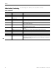
Appendix E Probability of Failure on Demand (PFD) and Probability of Failure per Hour (PFH) Data PFD Values Calculated PFD by Functional Test Interval Calculated PFD 2 Years 5 Years 10 Years (17,520 (43,800 (87,600 hours) hours) hours) 5.5E-06 Not applicable 20 Years (175,200 hours) 1.2E-05 Compact GuardLogix Controller 1.1E-06 2.7E-06 5.7E-06 1.2E-05 6.013E-06(1) 1.70E-05 Cat. No.
Glossary Add-On Instruction An instruction that you create as an add-on to the Logix instruction set. Once defined, an Add-On Instruction can be used like any other Logix instruction and can be used across various projects. An Add-On Instruction is composed of parameters, local tags, logic routine, and optional scan mode routines.
Glossary Online Situation where you are monitoring/modifying the program in the controller. Overlap When a task (periodic or event) is triggered while the task is still executing from the previous trigger. Partnership The primary controller and safety partner must both be present, and the hardware and firmware must be compatible for partnership to be established.
Glossary Routine A set of logic instructions in a single programming language, such as a ladder diagram. Routines provide executable code for the project in a controller. Each program has a main routine. You can also specify optional routines. Safety Add-On Instruction An Add-On Instruction that can use safety application instructions.
Glossary Safety Program A safety program has all the attributes of a standard program, except that it can only be scheduled in a safety task. The safety program consists of zero or more safety routines. It cannot contain standard routines or standard tags.
Glossary Safety Task Watchdog The maximum time allowed from the start of safety task execution to its completion. Exceeding the safety task Watchdog triggers a nonrecoverable safety fault. Standard Component Any object, task, tag, program, and so on, that is not marked as being a safety-related item. Standard Controller As used in this document, standard controller refers generically to a ControlLogix controller.
Glossary Notes: 108 Publication 1756-RM093F-EN-P - January 2010
Index Numerics 1734-AENT 16, 17 hardware overview 26 1734-AENTR 16 1756-A10 17 1756-A13 17 1756-A17 17 1756-A4 17 1756-A7 17 1756-CN2 firmware revision 17 hardware overview 26 1756-CN2R firmware revision 17 1756-DNB firmware revision 17 hardware overview 26 1756-EN2F firmware revision 17 1756-EN2T firmware revision 17 1756-ENBT firmware revision 17 hardware overview 26 1756-PA72 17 1756-PA75 17 1756-PA75R 17 1756-PB72 17 1756-PB75 17 1756-PB75R 17 1768-CNB 16 hardware overview 26 1768-CNBR hardware overview
Index EtherNet/IP communication interface module hardware overview 26 European norm.
Index program checklist 99 download 61 editing life cycle 65 offline editing 64 online editing 64 upload 61 program compare utility 59 program indentification 56 program verification 57 programming software 13 project confirmation 58 proof tests 14 see functional verification tests Q qualifying standard data 51 R reaction time safety task 21 system 21 recoverable faults 76, 104 reliability burden 20 requested packet interval definition 104 RSLogix 5000 software changing your application program 63 commis
Index signature history 87 software changing your application program 63 commissioning life cycle 54 system reaction time 21 calculating 89 definition 107 T tags produced/consumed safety data 50 Safety I/O 50 see also safety tags terminology used throughout manual 10 timeout multiplier definition 107 U UL 18 unique node reference defined 36 112 Publication 1756-RM093F-EN-P - January 2010
Rockwell Automation Support Rockwell Automation provides technical information on the Web to assist you in using its products. At http://www.rockwellautomation.com/support/, you can find technical manuals, a knowledge base of FAQs, technical and application notes, sample code and links to software service packs, and a MySupport feature that you can customize to make the best use of these tools.