POINT I/O EtherNet/IP Adapter Module 1734-AENT User Manual
Important User Information Because of the variety of uses for the products described in this publication, those responsible for the application and use of these products must satisfy themselves that all necessary steps have been taken to assure that each application and use meets all performance and safety requirements, including any applicable laws, regulations, codes and standards.
Preface What this Preface Contains This preface describes how to use this manual. The following table lists where to find specific information within this chapter.
Preface 2 TIP How To Use This Manual This symbol identifies helpful tips. This manual contains an overview of the 1734-AENT adapter. It describes how to install and configure the adapter, and provides examples showing how to use the adapter to communicate with POINT I/O over an EtherNet/IP network. About the Example Applications This manual presents two example applications that demonstrate the procedures for configuring and communicating with POINT I/O using the 1734-AENT adapter.
Preface 3 System Components We used the following components for the example applications. You will need the same or similar components to set up your own control system using PONT I/O on EtherNet/IP.
Preface 4 Refer to the following Rockwell publications as needed for additional help when setting up and using your EtherNet/IP network.
Preface For information about See this publication Publication number POINT I/O 22V ac input module POINT I/O 220V ac Input Module Installation Instructions 1734-IN008 POINT I/O RTD input module POINT I/O RTD Input Module Installation Instructions 1734-IN012 POINT I/O isolated termocouple input module POINT I/O Isolated Thermocouple Input Module 1734-IN011 POINT I/O termocouple and RTD input module Thermocouple and RTD Input Module User Manual 1734-UM004 POINT I/O IV2 and IV4 input module P
Preface 6 Terminology Refer to the table below for the meaning of common terms. This term Means BootP BootP (Bootstrap Protocol) is a low-level protocol that provides configurations to other nodes on a TCP/IP network. BootP configuration files let you automatically assign IP addresses to an Ethernet module (you can also obtain Subnet masks and gateway addresses from BootP). bridge A node between two similar communication subnets where protocol translation is minimal.
Preface This term Means Ethernet network A local area network designed for the high-speed exchange of information between computers and related devices. explicit messaging Non-time critical messaging used for device configuration and data collection, such as downloading programs or peer-to-peer messaging between two PLCs. full duplex A mode of communication that allows a device to send and receive information at the same time, effectively doubling the bandwidth.
Preface 8 Publication 1734-UM011A-EN-P - February 2004 This term Means latency The time between initiating a request for data and the beginning of the actual data transfer. multicast In the CIP producer/consumer model one producer multicasts (broadcasts) the data once to all the consumers. producer The source of information in the CIP networking model. See CIP. rack optimized A physical and logical collection of application modules.
Table of Contents Chapter 1 About the 1734-AENT Adapter What This Chapter Contains . . . . . . . . . . . . . . . . . . . . . . . . . . . . . . . Important Adapter Considerations . . . . . . . . . . . . . . . . . . . . . . . . . . Set the Chassis Size . . . . . . . . . . . . . . . . . . . . . . . . . . . . . . . . . . . Adapter replacement . . . . . . . . . . . . . . . . . . . . . . . . . . . . . . . . . . Empty Slots and RIUP Situations. . . . . . . . . . . . . . . . . . . . . . . .
Table of Contents ii Chapter 4 Configure the 1734-AENT for Direct Connection in RSLogix 5000 About the Example Application . . . . . . . . . . . . . . . . . . . . . . . . . . . . 4--1 Set Up the Hardware . . . . . . . . . . . . . . . . . . . . . . . . . . . . . . . . . . . . . 4--2 Create the Example Application . . . . . . . . . . . . . . . . . . . . . . . . . . . . 4--3 Configure the I/O . . . . . . . . . . . . . . . . . . . . . . . . . . . . . . . . . . . . . . .
Table of Contents iii Appendix A 1734-AENT Adapter Web Pages Web Page Diagnostics . . . . . . . . . . . . . . . . . . . . . . . . . . . . . . . . . . . . A--1 Diagnostic Information . . . . . . . . . . . . . . . . . . . . . . . . . . . . . . . . Module Information . . . . . . . . . . . . . . . . . . . . . . . . . . . . . . . . . . EDS Files . . . . . . . . . . . . . . . . . . . . . . . . . . . . . . . . . . . . . . . . . . . Network Statistics . . . . . . . . . . . . . . . . . . . . . . . . . . . . . . .
Table of Contents iv Publication 1734-UM011A-EN-P - February 2004
Chapter 1 About the 1734-AENT Adapter What This Chapter Contains This chapter provides an overview of the 1734-AENT POINT I/O EtherNet/IP adapter, its primary features, and how to use it. You will need to understand the concepts discussed in this chapter to configure your adapter and use it in an EtherNet/IP control system. The following table lists where to find specific information in this chapter.
1-2 About the 1734-AENT Adapter Important Adapter Considerations Before you begin using your 1734-AENT, please note the following important considerations. Set the Chassis Size The 1734-AENT POINT I/O adapter for EtherNet/IP requires its chassis size to be configured before any I/O connections can be made. The default setting for the chassis size is 1 slot which represents the adapter by itself.
About the 1734-AENT Adapter 1-3 Empty Slots and RIUP Situations The POINT I/O system does not have the ability to detect an empty terminal base. Because of this, there are numerous situations in which you can potentially configure a system that is unusable or one that exercises unintended control. In an attempt to address these situations, you must observe the following rules for POINT I/O system construction and the removal and reinsertion of modules.
1-4 About the 1734-AENT Adapter Power Up a System For the First Time When POINT I/O is powered for the first time, the adapter must assign addresses to every module in the backplane. POINT I/O modules all ship configured at the same address. Therefore, at first power up, it is expected that all but one module on the backplane will exhibit a solid red Module Status LED. One by one the adapter will reset these modules and address them appropriately.
About the 1734-AENT Adapter Hardware/Software Compatibility What the Adapter Does 1-5 The 1734-AENT adapter and the applications described in this manual are compatible with the following firmware versions and software releases. Contact Rockwell Automation if you need software or firmware upgrades to use this equipment. Product Firmware Version/ Software Release 1734-AENT Adapter 1.xx or higher 1756-ENBT 2.3 or higher Logix 5555 Controller 11 or higher RSLogix 5000 software 11.
1-6 About the 1734-AENT Adapter This has two significant benefits: • You do not need to configure routing tables in the bridging modules, which greatly simplifies maintenance and module replacement. • You maintain full control over the route taken by each message, which enables you to select alternative paths for the same end device. Understand the Producer/Consumer Model The CIP “producer/consumer” networking model replaces the old source/destination (“master/slave”) model.
About the 1734-AENT Adapter 1-7 from more than one I/O module into a single block of data sent over a single connection at the same data rate. Rack optimized connections reduce the total number of connections needed to transfer data when using many I/O modules in a system. The following example illustrates the benefit of rack optimized connections. Assume you have set up a system that contains 8 discrete I/O modules interfaced to a 1734-AENT adapter.
1-8 About the 1734-AENT Adapter What’s Next? Publication 1734-UM011A-EN-P - February 2004 The following chapter describes how to physically install the 1734-AENT adapter and connect it to the EtherNet/IP network.
Chapter 2 Install the 1734-AENT Adapter What This Chapter Contains This chapter describes how to physically install the 1734-AENT adapter on the DIN rail and connect it to the EtherNet/IP network. The following table lists where to find specific information.
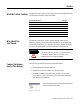
2-2 Install the 1734-AENT Adapter Identify Module Components Use the following illustration to identify the external features of the POINT I/O EtherNet/IP adapter.
Install the 1734-AENT Adapter 2-3 3. Set the network address thumbwheel switches to the desired value (see Set the Network Address on page 3--6 in the next chapter). WARNING If you connect or disconnect the Ethernet cable with power applied to this module or any device on the network, an electrical arc can occur. This could cause an explosion in hazardous location installations. Be sure that power is removed or the area is nonhazardous before proceeding. 4. Slide the safety end cap up to remove it.
2-4 Install the 1734-AENT Adapter 7. Set the network address thumbwheel switches to the value used on the replaced module (see Set the Network Address on page 3--6 in the next chapter). 8. Insert the end of the terminal block (RTB) opposite the handle into the base unit. This end has a curved section that engages with the wiring base. 9. Rotate the terminal block into the wiring base until it locks itself into place.
Install the 1734-AENT Adapter Mounting Dimensions inches (millimeters) 2-5 2.16 (54.9) 3.0 (76.5) 1.44 (36.51) 5.25 (133.4) B A 43520 A = DIN rail B = Secure DIN rail approximately every 200mm What’s Next? 1734-AENT 3.0H x 2.16W x 5.25D (76.2H x 54.9W x 133.4D) The following chapter describes how to configure the adapter to communicate on your EtherNet/IP network by providing an IP address, Gateway address, and Subnet mask.
2-6 Install the 1734-AENT Adapter Notes: Publication 1734-UM011A-EN-P - February 2004
Chapter 3 Configure the 1734-AENT Adapter for Your EtherNet/IP Network What This Chapter Contains Before you can use your 1734-AENT adapter in an EtherNet/IP network you must configure it with an IP address, Subnet mask, and optional Gateway address. This chapter describes these configuration requirements and the procedures for providing them. There are several way you can do this: • Using the Rockwell BootP utility, version 2.3 or greater, that ships with RSLogix 5000 or RSLinx software.
3-2 Configure the 1734-AENT Adapter for Your EtherNet/IP Network Before you can use your 1734-AENT adapter, you must configure its IP address, its subnet mask, and optionally, gateway address. You can use the Rockwell BootP utility, version 2.3 or greater, to perform the configuration. You can also use a DHCP server or the network address switches to configure these parameters. Configuration Requirements If the 1734-AENT needs to be reset to factory defaults, see the Important note on page A--9.
Configure the 1734-AENT Adapter for Your EtherNet/IP Network 3-3 You can distinguish the class of the IP address from the first integer in its dotted-decimal IP address as follows: Range of first integer Class Range of first integer Class 0 -127 A 192 - 223 C 128 -191 B 224 - 255 other Each node on the same physical network must have an IP address of the same class and must have the same net ID. Each node on the same network must have a different Host ID thus giving it a unique IP address.
3-4 Configure the 1734-AENT Adapter for Your EtherNet/IP Network When host B communicates with host A, it knows from A’s IP address that A is on another network (the net IDs are different). In order to send data to A, B must have the IP address of the gateway connecting the two networks. In this example, the gateway’s IP address on Network 2 is 128.2.0.3. The gateway has two IP addresses (128.1.0.2 and 128.2.0.3).
Configure the 1734-AENT Adapter for Your EtherNet/IP Network 3-5 The new configuration is: A 128.1.0.1 Network 1 128.1.0.2 G C B 128.2.64.1 128.2.64.3 128.2.64.2 Network 2.1 G2 D E 128.2.128.1 128.2.128.3 128.2.128.2 Network 2.2 A second network with Hosts D and E has been added. Gateway G2 connects Network 2.1 with Network 2.2. Hosts D and E will use Gateway G2 to communicate with hosts not on Network 2.2. Hosts B and C will use Gateway G to communicate with hosts not on Network 2.1.
3-6 Configure the 1734-AENT Adapter for Your EtherNet/IP Network Set the Network Address You can set the network Internet Protocol (IP) address 3 different ways: 1. Using the thumbwheel switches located on the module 2. Using a Dynamic Host Configuration Protocol (DHCP) server, such as Rockwell Automation BootP/DHCP 3. Retrieving the IP address from nonvolatile memory. Module Status 0 0 2 Network Address Thumbwheel Press either the + or buttons to change the number.
Configure the 1734-AENT Adapter for Your EtherNet/IP Network Use the Rockwell BootP/DHCP Utility 3-7 The Rockwell BootP/DHCP utility is a stand alone program that incorporates the functionality of standard BootP software with a user friendly graphical interface. It is located in the Utils directory on the RSLogix 5000 installation CD. The 1734-AENT adapter must have DHCP enabled (factory default and the network address switches set to an illegal value) to use the utility.
3-8 Configure the 1734-AENT Adapter for Your EtherNet/IP Network The device will be added to the Relation List, displaying the Ethernet Address (MAC) and corresponding IP Address, Hostname and Description (if applicable). When the address displays in the IP Address column in the Request History section, it signifies that the IP address assignment has been made. 4. To assign this configuration to the device, highlight the device in the Relation List panel and click on the Disable BOOTP/DHCP button.
Configure the 1734-AENT Adapter for Your EtherNet/IP Network 3-9 Save the Relation List You can save the Relation List to use later. To save the Relation List perform the following steps: 1. Select Save As... from the File menu. You will see the following window. 2. Select the folder you want to Save in: 3. Enter a File name for the Relation List (e.g., “control system configuration”) and click on Save. You can leave the Save as type at the default setting: “Bootp Config Files (*.bpc)”.
3-10 Configure the 1734-AENT Adapter for Your EtherNet/IP Network You can then open the file containing the Relation List at a later session. Use DHCP Software to Configure Your Adapter DHCP (Dynamic Host Configuration Protocol) software automatically assigns IP addresses to client stations logging onto a TCP/IP network. DHCP is based on BootP and maintains some backward compatibility.
Chapter 4 Configure the 1734-AENT for Direct Connection in RSLogix 5000 About the Example Application In this example, a ControlLogix processor communicates with POINT I/O via the 1734-AENT adapter using a direct connection. The adapter will make a direct connection to each of the modules referenced by the data. Note that the modules presented in this chapter are configured using RSLogix 5000, version 11.
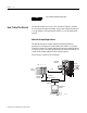
4-2 Configure the 1734-AENT for Direct Connection in RSLogix 5000 Set Up the Hardware In this example, a ControlLogix chassis contains the Logix 5555 processor in slot 1 and a 1756-ENBT bridge module in slot 3. The 1734-AENT adapter is mounted on a DIN rail in slot 0, with a 1734-OW2/C relay output module in slot 1, a 1734-OV4E/C sink output module in slot 2, and a power supply (not shown). 1734-AENT 10.88.70.2 POINT I/O Slot 0 1 2 3 Local Chassis Data Logix5555 Controller (slot 1) 1756-ENBT 10.88.
Configure the 1734-AENT for Direct Connection in RSLogix 5000 Create the Example Application 4-3 Perform the following steps to create the example application: 1. Start RSLogix 5000 Enterprise Series. The RSLogix 5000 Main Window will open. 2. From the File menu, select New. The New Controller pop-up window will open. 3. Enter an appropriate Name for the Controller, e.g., “POINT_IO_Controller.” 4.
4-4 Configure the 1734-AENT for Direct Connection in RSLogix 5000 5. Click on OK. Configure the I/O You now add the POINT I/O modules to the controller’s I/O configuration. To do this you first add the local 1756-ENBT module to the I/O configuration. Next you add the 1734-AENT adapter as a “child” of the 1756-ENBT module. Then you add the I/O modules as “children” of the 1734-AENT adapter.
Configure the 1734-AENT for Direct Connection in RSLogix 5000 4-5 The Select Module Type window will open. 3. Select the 1756-ENBT EtherNet/IP Bridge and click on OK. The Module Properties window will open. 4. We used the following values: Name Local_ENB IP Address 10.88.70.4 Slot 3 Electronic Keying Compatible Module Revision 1.1 5. Click on Finish to accept the configuration.
4-6 Configure the 1734-AENT for Direct Connection in RSLogix 5000 Add the POINT I/O Adapter to the I/O Configuration Next, you must add the 1734-AENT adapter as a “child” of the local 1756-ENBT module. 1. In the Project window, right click on the local 1756-ENBT module under the I/O Configuration folder and select New Module from the pop-up window. The Select Module Type window will open. 2. Select the 1734-AENT/A Ethernet adapter from the list and click on OK.
Configure the 1734-AENT for Direct Connection in RSLogix 5000 4-7 The Module Properties window will open. 3. We used the following values: Name POINT_IO_Adapter IP Address 10.88.70.2 Comm Format None Chassis Size 3 Electronic Keying Compatible Module Revision 1.1 Note that the Slot field is disabled because the slot is automatically 0 for the 1734-AENT.
4-8 Configure the 1734-AENT for Direct Connection in RSLogix 5000 Because None was entered as the Comm Format on the Module Properties window, the RPI (requested packet interval) is disabled. 5. Click on the Finish button to accept the configuration. The 1734-AENT adapter will appear indented under the local 1734-ENBT in the I/O Configuration folder. Add the POINT I/O Modules to the I/O Configuration You must now add the POINT I/O modules to the I/O Configuration List under the 1734-AENT adapter.
Configure the 1734-AENT for Direct Connection in RSLogix 5000 4-9 The Select Module Type window will open. 2. Select the 1734-OW2/C relay output module from the list and click on OK. At the bottom of the Select Module Type screen, you can choose Clear All and then select a type of module (analog, digital, specialty) to narrow your search. TIP The Module Properties window will open. 3.
4-10 Configure the 1734-AENT for Direct Connection in RSLogix 5000 The Comm Format is Output Data, indicating a direct connection, because on the adapter’s property window, we set the Comm Format to None. If you are using a discrete input module, then the Comm Format would be Input Data. 4. Choose Next. Notice that RPI is selectable on the screen below since it is a direct connection. 5. Enter the RPI (requested packet interval) to set how often the data is exchanged with the 1734-AENT.
Configure the 1734-AENT for Direct Connection in RSLogix 5000 4-11 7. Click on the Finish button to save the configuration. The relay output module will appear in the I/O configuration indented under the 1734-AENT adapter. Add the Digital Output Module 8. Right click on the 1734-AENT adapter and again select New Module. The Select Module Type window will open. 9. Select the 1734-OV4E/C digital output module from the list.
4-12 Configure the 1734-AENT for Direct Connection in RSLogix 5000 The Module Properties window will open. 10. We used the following values: Name POINT_Digital_Output Slot 2 Comm Format Output Data Electronic Keying Compatible Module Revision 3.1 11. Click the Next button. 12. Leave 10 ms. as the RPI for the 1734-OV4E module. 13. Click on the Finish button to accept the configuration. The I/O Configuration in the Project window should look similar to the one shown below.
Configure the 1734-AENT for Direct Connection in RSLogix 5000 Edit the Controller Tags 4-13 When you add modules to the I/O configuration the system creates tags for those modules to use in the application program. For the example application you need to add one more Controller Tag. 1. Double-click on the Controller Tags folder in the project window. The Controller Tags window will open. You will see the tags created for the 1734-AENT and digital I/O modules.
4-14 Configure the 1734-AENT for Direct Connection in RSLogix 5000 3. Close the Controller Tags window. Create the Ladder Program Next create the example ladder program to test the I/O. 1. Double-click on Main Routine under the Main Program folder. 2. Enter the following ladder program using the tags previously created. 3. Save the program.
Configure the 1734-AENT for Direct Connection in RSLogix 5000 Download the Program to the Controller 4-15 Follow this procedure to download the program we just saved to the ControlLogix controller. 1. From the main menu, choose Communications>Who-Active. 2. Navigate to select the slot where the processor is located in the chassis. 3. Choose Set Project Path. 4. Choose Download. 5. Choose Download. You see this window.
4-16 Configure the 1734-AENT for Direct Connection in RSLogix 5000 Notice that the 1756-ENBT Bridge is now online. If yellow triangles are present, see the following section. Verify the Module Chassis Size You have now built the I/O tree in RSLogix 5000, and the RSLogix 5000 software used the chassis size from the 1734-AENT General tab. Now you need to download this new chassis size value into the 1734-AENT adapter hardware.
Configure the 1734-AENT for Direct Connection in RSLogix 5000 4-17 6. Click Set Chassis Size in Module. Value from RSLogix 5000 Value stored in 1734-AENT 7. Read and acknowledge the warning screen. 8. Click OK to continue. Notice the chassis size in the module has been modified to 3.
4-18 Configure the 1734-AENT for Direct Connection in RSLogix 5000 9. Click OK. At this point, your PointBus status LED should be solid green. All the yellow triangles in your I/O configuration should be gone. Configure the 1734-AENT with Fixed IP Address To configure the 1734-AENT with a fixed IP address to prevent the adapter from ceasing to communicate with the ControlLogix controller: 1. Click on the Port Configuration tab in the 1734-AENT properties window. 2.
Configure the 1734-AENT for Direct Connection in RSLogix 5000 An Overloaded 1734-AENT 4-19 Each POINT I/O connection established with the 1734-AENT will consume a portion of the microprocessor’s bandwidth. The amount of bandwidth used by a connection depends on a number of variables, including the Requested Packet Interval (RPI), the number of POINT I/O modules involved in the connection, and the rate of change of the I/O.
4-20 Configure the 1734-AENT for Direct Connection in RSLogix 5000 Notes: Publication 1734-UM011A-EN-P - February 2004
Chapter 5 Configure the 1734-AENT for Direct Connection and Rack Optimization in RSLogix 5000 What’s in This Chapter This chapter guides you through the steps required to configure your 1734 POINT I/O Ethernet Adapter for both direct connection and rack optimization using RSLogix 5000. You can mix communication formats for different I/O modules communicating through the same adapter. I/O modules set up to use rack optimization will communicate at the rate of the RPI configured for the 1734-AENT adapter.
5-2 Configure the 1734-AENT for Direct Connection and Rack Optimization in RSLogix 5000 Set Up the Hardware In this example, a ControlLogix chassis contains the Logix 5555 processor in slot 1 and a 1756-ENBT bridge module in slot 3. The 1734-AENT adapter is mounted on a DIN rail in slot 0, with a 1734-OW2/C relay output module in slot 1, a 1734-OV4E/C sink output module in slot 2, and a power supply (not shown). 1734-AENT 10.88.70.
Configure the 1734-AENT for Direct Connection and Rack Optimization in RSLogix 5000 Create the Example Application 5-3 Perform the following steps to create the example application: 1. Start RSLogix 5000 Enterprise Series. The RSLogix 5000 Main Window will open. 2. From the File menu, select New. The New Controller pop-up window will open. 3. Enter an appropriate Name for the Controller, e.g., “POINT_IO_Controller.” 4.
5-4 Configure the 1734-AENT for Direct Connection and Rack Optimization in RSLogix 5000 Click on OK. Configure the I/O You now add the POINT I/O modules to the controller’s I/O configuration. To do this you first add the local 1756-ENBT module to the I/O configuration. Next you add the 1734-AENT adapter as a “child” of the 1756-ENBT module. Then you add the I/O modules as “children” of the 1734-AENT adapter.
Configure the 1734-AENT for Direct Connection and Rack Optimization in RSLogix 5000 5-5 The Select Module Type window will open. 3. Select the 1756-ENBT EtherNet/IP Bridge and click on OK. The Module Properties window will open. 4. We used the following values: Name Local_ENB IP Address 10.88.70.4 Slot 3 Electronic Keying Compatible Module Revision 1.1 5. Click on Finish to accept the configuration.
5-6 Configure the 1734-AENT for Direct Connection and Rack Optimization in RSLogix 5000 Add the POINT I/O Adapter to the I/O Configuration Next, you must add the 1734-AENT adapter as a “child” of the local 1756-ENBT module. 1. In the Project window, right click on the local 1756-ENBT module under the I/O Configuration folder and select New Module from the pop-up window. The Select Module Type window will open. 2. Select the 1734-AENT/A Ethernet adapter from the list and click on OK.
Configure the 1734-AENT for Direct Connection and Rack Optimization in RSLogix 5000 5-7 The Module Properties window will open. 3. We used the following values: Name POINT_IO_Adapter IP Address 10.88.70.2 Comm Format Rack Optimization Chassis Size 3 Electronic Keying Compatible Module Revision 1.1 Note that the Slot field is disabled because the slot is automatically 0 for the 1734-AENT.
5-8 Configure the 1734-AENT for Direct Connection and Rack Optimization in RSLogix 5000 The following window will open: 5. Verify that the Requested Packet Interval (RPI) is appropriate for your system (10 ms for this example). This will be used for the rack optimized connection to the I/O modules. IMPORTANT To avoid overloading the 1734-AENT, it is recommended that the RPI be no less than 10 ms for rack connections and 50 ms for direct connections. 6.
Configure the 1734-AENT for Direct Connection and Rack Optimization in RSLogix 5000 TIP 5-9 At the bottom of the Select Module Type screen, you can choose Clear All and then select a type of module (analog, digital, specialty) to narrow your search. 3. Click OK. The Module Properties window will open. 4. Enter a Name (optional), Slot Number, and the Comm Format.
5-10 Configure the 1734-AENT for Direct Connection and Rack Optimization in RSLogix 5000 Notice that RPI is selectable on the screen below since it is a direct connection. 6. Enter the RPI (requested packet interval) to set how often the data is exchanged with the 1734-AENT. IMPORTANT To avoid overloading the 1734-AENT, it is recommended that the RPI be no less than 10 ms for rack connections and 50 ms for direct connections. 7. Enter 50 for the RPI. 8. Choose Finish.
Configure the 1734-AENT for Direct Connection and Rack Optimization in RSLogix 5000 5-11 Add the POINT I/O Module and Configure For Rack Optimization 1. Highlight the 1734-AENT under I/O Configuration, right click and select New Module. The Select Module Type window will open. 2. Choose the 1734-OV4E/C module. 3. Click OK. The Module Properties window will open. 4. Enter a Name, Slot, Comm Format, and Comm Format.
5-12 Configure the 1734-AENT for Direct Connection and Rack Optimization in RSLogix 5000 The output data for the 1734-OW2 is a separate and distinct module on the network. The 1734-OV4E is part of the rack connection. 5. Click on the Finish button to accept the configuration. The I/O Configuration in the Project window should look similar to the one shown below. 6. Choose Finish. 7. Choose File>Save and enter the name and location of the RSLogix 5000 file.
Configure the 1734-AENT for Direct Connection and Rack Optimization in RSLogix 5000 5-13 5. Choose Download. You see this window. Notice that the 1756-ENBT Bridge is now online. If yellow triangles are present, see the following section. Verify the Module Chassis Size You have now built the I/O tree in RSLogix 5000, and the RSLogix 5000 software used the chassis size from the 1734-AENT General tab. Now you need to download this new chassis size value into the 1734-AENT adapter hardware.
5-14 Configure the 1734-AENT for Direct Connection and Rack Optimization in RSLogix 5000 You see the Module Fault error code. 5. Click the Chassis Size tab. 6. Click Set Chassis Size in Module. Value from RSLogix 5000 Value stored in 1734-AENT 7. Read and acknowledge the warning screen.
Configure the 1734-AENT for Direct Connection and Rack Optimization in RSLogix 5000 5-15 8. Click OK to continue. Notice the chassis size in the module has been modified to 3. 9. Click OK. At this point, you PointBus status LED should be solid green. All the yellow triangles in your I/O configuration should be gone. 10. Click OK to close the window. 11. Click File>Save to save the project.
5-16 Configure the 1734-AENT for Direct Connection and Rack Optimization in RSLogix 5000 Access Module Data via the 1734-AENT Adapter Use the following information to use the 1734 POINT I/O Ethernet adapter module data in the ladder logic program. • POINT_IO_Adapter = the name you gave to your Ethernet adapter • # = slot number of POINT I/O module • C = configuration, I = input, O = output This value indicates that slot 2 is the only module participating in the rack optimized connection with no errors.
Chapter 6 LED Status Indicators ATTENTION You must use Series C POINT I/O modules with the 1734-AENT adapter. Series A or B POINT I/O modules will not work with this adapter.
6-2 LED Status Indicators Indication Probable Cause Solid Red Unrecoverable fault has occurred: • Self-test failure (checksum failure, or ramtest failure at powerup) • Firmware fatal error Network Status Off Device not initialized. The module does not have an IP address Flashing Green No CIP connections. Device has an IP address, but no CIP connections are established Green CIP connections.
Chapter 7 Safety Approvals and Specifications ATTENTION You must use Series C POINT I/O modules with the 1734-AENT adapter. Series A or B POINT I/O modules will not work with this adapter. Safety Approval information for the 1734-AENT is below.
7-2 Safety Approvals and Specifications Specifications Specifications information for the 1734-AENT is below. Specifications - 1734-AENT EtherNet/IP Adapter Expansion I/O Capacity Maximum of 63 modules Maximum of 5 Rack Optimized connections (for digital modules only) Maximum of 25 direct connections 1734-AENT backplane current output = 1.0A. The actual number of modules can vary. Add up the current requirements of the modules you want to use to make sure they do not exceed the amperage limit of 1.
Safety Approvals and Specifications 7-3 General Specifications Indicators 3 red/green status indicators Adapter status PointBus status Network status 3 green status indicators: Network activity status System Power (PointBus 5V power) Field Power (24V from field supply) Power Consumption 4.5W maximum @ 28.8V dc Power Dissipation 15.5W maximum @ 28.8V PointBus Output Current 1A maximum @ 5V dc ±5% (4.75 - 5.25) Input Overvoltage Reverse polarity protected Protection Thermal Dissipation 9.
7-4 Surge Transient Immunity Conducted RF Immunity Emissions Enclosure Type Rating Conductors Wire Size Category IEC 61000-4-5: +1kV line-line(DM) and +2kV line-earth(CM) on signal ports +1kV line-line(DM) and +2kV line-earth(CM) on power ports IEC 61000-4-6: 10Vrms with 1kHz sine-wave 80%AM from 150kHz to 80MHz CISPR 11: Group 1, Class A None (open-style) 14- 22 AWG (2.5-0.25mm2) solid or stranded wire rated at 75oC or higher 3/64 inch (1.2mm) insulation maximum 21 RJ-45, Category 5 7 pound-inches (0.
Appendix A 1734-AENT Adapter Web Pages Web Page Diagnostics The 1734-AENT adapter’s Web pages offer extensive internal and network diagnostics. To view the Web pages, enter the adapter’s IP address into Netscape or Microsoft Internet Explorer. You will see the Web page shown below: IMPORTANT Make sure that your PC Internet LAN setting and your TCP/IP settings are configured to access the subnet on which your adapter communicates.
A-2 1734-AENT Adapter Web Pages Diagnostic Information From the Diagnostic Home page you can access other diagnostic web pages, including: • • • • Publication 1734-UM011A-EN-P - February 2004 Module Information Detailed Network Statistics Connection Information Diagnostic Messaging
1734-AENT Adapter Web Pages A-3 Module Information On the Module Information page, you can obtain module specifications, such as the module name, module uptime information, vendor ID, product type, product code, firmware revision, status switches, and CPU utilization. EDS Files You can access the 1734-AENT EDS files from the Module Information page. These EDS files are coming from your adapter. You can also be directed to access other modules’ EDS files from the Module Information page.
A-4 1734-AENT Adapter Web Pages Network Statistics The Network Statistics page provides information that echoes the state of The Network Statistics page provides information that echoes the state of the module.
1734-AENT Adapter Web Pages A-5 Connection Statistics The Connection Statistics page list CIP-related statistic and connection activity.
A-6 1734-AENT Adapter Web Pages Diagnostic Messaging The Diagnostic Messaging page lets you retrieve module status or conditions, such as: • • • • • • Publication 1734-UM011A-EN-P - February 2004 Service I/O slot position Class Instance Attribute Timeout
1734-AENT Adapter Web Pages A-7 Browse Chassis Browse the chassis to see what modules are present on the system. A query will run from slot 1 to slot 63. The Browse Chassis page will display the modules that were found based on this query. The Browse Chassis page provides an easy and helpful way to see what modules the adapter is recognizing on your system. • Select the Display compact button so a check mark appears to decrease the font size. This may make it easier to read the screen.
A-8 1734-AENT Adapter Web Pages Configuration The Configuration page provides a way for you to configure the TCP/IP parameters for your adapter, such as, Host Name, IP Address, Gateway Address, Subnet Mask, etc. By default, the password for the screen is password (case sensitive). Once you enter the password and click the Submit button, you can enter a new password. Click the Change button to accept the new password.
1734-AENT Adapter Web Pages IMPORTANT A-9 If you set the thumbwheels on the 1734-AENT to the value 888 and then power cycle the module, the following will occur: • the DHCP Enabled function will be enabled (set to True) • the Ethernet link will be negotiated automatically (the Auto Negotiate function will be set to True) • the web server will be enabled (the Disabled Web Server function will be disabled) • the password for this page will reset to the factory default (the word "password" is the factory de
A-10 1734-AENT Adapter Web Pages Notes: Publication 1734-UM011A-EN-P - February 2004
Appendix B Configure the RSLinx Ethernet Communication Driver What This Appendix Contains In order to communicate with your 1734-AENT adapter over your network you must configure the RSLinx Ethernet communication driver (AB_ETH) or the EtherNet/IP driver (AB-ETHIP). You can configure the AB_ETH driver with the IP addresses of all the Ethernet devices on your system. You will need one of these drivers to download the example application programs in this manual.
B-2 Configure the RSLinx Ethernet Communication Driver You will see the progress bar, followed by the welcome screen. Configure the AB_ETH Driver To configure the AB-ETH Ethernet communication driver perform the following steps: 1. Start RSLinx. 2. From the Communications menu, select Configure Drivers. 3. Click on the arrow to the right of the Available Driver Types box. The Available Driver Types list will appear. 4. Select Ethernet Devices and click on Add/New.
Configure the RSLinx Ethernet Communication Driver B-3 You will be prompted to name the driver. 5. Select the default driver name (e.g., AB_ETH-1) or type in your own name and click on OK. The Configure driver window will appear with the Station Mapping page open. 6. Click on Add New and enter the IP address or Host Name of your Ethernet device (e.g., 10.88.70.4, “Pump1”, etc.). 7. Repeat step 6 for each additional Ethernet device you need to access. 8.
B-4 Configure the RSLinx Ethernet Communication Driver The new driver will appear in the list of configured drivers. (Your list will display the drivers you have configured on your workstation.) 9. Close RSLinx. Configure the AB_ETH/IP Driver To configure the AB-ETHIP Ethernet communication driver perform the following steps: 1. Start RSLinx. 2. From the Communications menu, select Configure Drivers. 3. Click on the arrow to the right of the Available Driver Types box.
Configure the RSLinx Ethernet Communication Driver B-5 4. Select EtherNet/IP Devices and click on Add/New. You see this window. 5. Make sure the Browse Local Subnet button is selected.
B-6 Configure the RSLinx Ethernet Communication Driver RSLinx will browse your local subnet and automatically read the IP address. 6. Click OK. The AB-ETHIP driver is now configured and appears in the configured drivers window. 7. Close RSLinx.
Appendix C 1734-POINT I/O Module/RSLogix 5000 Controller Tag Reference ATTENTION You must use Series C POINT I/O modules with the 1734-AENT adapter. Series A or B POINT I/O modules will not work with this adapter.
C-2 1734-POINT I/O Module/RSLogix 5000 Controller Tag Reference 1734 POINT I/O Catalog Number RSLogix5000 Module Description Specialty I/O 1734-232ASC/C 1 Channel ASCII Interface Module 1734-IJ/C 1 Channel 5V DC Encoder/Counter 1734-IK/C 1 Channel 15-24V DC Encoder/Counter 1734-SSI/C 1 Channel Synchronous Serial Interface 1734-VHSC24/C 1 Channel 15-24V DC Very High Speed Counter 1734-VHSC5/C 1 Channel 5V DC Very High Speed Counter Note that all POINT I/O modules must be Series C or above for
1734-POINT I/O Module/RSLogix 5000 Controller Tag Reference C-3 Discrete 2 POINT Input 1734-IA2 2 POINT 120V AC Input 1734-IB2 2 POINT 10V-28V DC Input, Sink 1734-IM2 2 POINT 240V AC Input 1734-IV2 2 POINT 10V-28V DC Input, Source Configuration Data Data Type Default Value Valid Data Values Filter Off On Time - POINT 0 INT 1,000 -32,768 to 32,767 µs * (0 - 65,535) Filter On Off Time - POINT 0 INT 1,000 -32,768 to 32,767 µs * (0 - 65,535) Filter Off On Time - POINT 1 INT 1,000 -32,768 to 32,
C-4 1734-POINT I/O Module/RSLogix 5000 Controller Tag Reference Discrete 4 POINT Input 1734-IB4 4 POINT 10V-28V DC Input, Sink 1734-IV4 4 POINT 10V-28V DC Input, Source Configuration Data Data Type Default Value Valid Data Values Filter Off On Time - POINT 0 INT 1,000 -32,768 to 32,767 µs * (0 - 65,535) Filter On Off Time - POINT 0 INT 1,000 -32,768 to 32,767 µs * (0 - 65,535) Filter Off On Time - POINT 1 INT 1,000 -32,768 to 32,767 µs * (0 - 65,535) Filter On Off Time - POINT 1 INT 1,00
1734-POINT I/O Module/RSLogix 5000 Controller Tag Reference C-5 Discrete 2 POINT Output – Without Diagnostic Status 1734-OA2 2 POINT 120V AC Output 1734-OW2 2 POINT AC/DC Relay Output 1734-OX2 2 POINT Relay Output N.O./N.C.
C-6 1734-POINT I/O Module/RSLogix 5000 Controller Tag Reference Discrete 2 POINT Output – With Over Load and Open Load Diagnostic Status 1734-OB2E 2 POINT 10V-28V DC Electronically Fused Output, Source 1734-OB2EP 2 POINT 10V-28V DC Electronically Fused Protected Output, Source Publication 1734-UM011A-EN-P - February 2004 Configuration Data Data Type Default Value Valid Data Values Fault Mode - POINT 0, 1 SINT, BIT 0 0=Fault Value 1=Hold Last State Fault Value - POINT 0, 1 SINT, BIT 0 0=Off 1
1734-POINT I/O Module/RSLogix 5000 Controller Tag Reference Discrete 2 POINT Output – With Over Load Diagnostic Status C-7 1734-OV2E 2 POINT 10V-28V DC Electronically Fused Output, Sink Configuration Data Data Type Default Value Valid Data Values Fault Mode - POINT 0, 1 SINT, BIT 0 0=Fault Value 1=Hold Last State Fault Value - POINT 0, 1 SINT, BIT 0 0=Off 1=On Program Mode - POINT 0, 1 SINT, BIT 0 0=Program Value 1=Hold Last State Program Value - POINT 0, 1 SINT, BIT 0 0=Off 1=On Auto
C-8 1734-POINT I/O Module/RSLogix 5000 Controller Tag Reference Discrete 4 POINT Output – With Over Load and Open Load Diagnostic Status Publication 1734-UM011A-EN-P - February 2004 1734-OB4E 4 POINT 10V-28V DC Electronically Fused Output, Source Configuration Data Data Type Default Valid Data Values Value Fault Mode - POINT 0, 1, 2, 3 SINT, BIT 0 0=Fault Value 1=Hold Last State Fault Value - POINT 0, 1, 2, 3 SINT, BIT 0 0=Off 1=On Program Mode - POINT 0, 1, 2, 3 SINT, BIT 0 0=Program Value
1734-POINT I/O Module/RSLogix 5000 Controller Tag Reference Discrete 4 POINT Output – With Over Load Diagnostic Status C-9 1734-OV4E 4 POINT 10V-28V DC Electronically Fused Output, Sink Configuration Data Data Type Default Valid Data Values Value Fault Mode - POINT 0, 1, 2, 3 SINT, BIT 0 0=Fault Value 1=Hold Last State Fault Value - POINT 0, 1, 2, 3 SINT, BIT 0 0=Off 1=On Program Mode - POINT 0, 1, 2, 3 SINT, BIT 0 0=Program Value 1=Hold Last State Program Value - POINT 0, 1, 2, 3 SINT, BI
C-10 1734-POINT I/O Module/RSLogix 5000 Controller Tag Reference Analog 2 Channel Input 1734-IE2C 2 Channel Analog Current Input Publication 1734-UM011A-EN-P - February 2004 Configuration Data Data Type Default Valid Data Values Value Low Engineering Channel 0 INT 3,277 -32,768 to 32,767 High Engineering Channel 0 INT 16,383 -32,768 to 32,767 Digital Filter Channel 0 INT 0 0 to 10,000 ms Low Alarm Limit Channel 0 INT 3,113 -32,768 to 32,767 High Alarm Limit Channel 0 INT 16,547 -32,
1734-POINT I/O Module/RSLogix 5000 Controller Tag Reference C-11 1734-IE2C 2 Channel Analog Current Input Input Data Data Type Default Value Valid Data Values Data Channel 0 INT 0 -32,768 to 32,767 Data Channel 1 INT 0 -32,768 to 32,767 Status Byte Channel 0 SINT 0 Bit 0 Fault Bit 1 Calibration Bit 2 LowAlarm Bit 3 HighAlarm Bit 4 LowLowAlarm Bit 5 HighHighAlarm Bit 6 Underrange Bit 7 Overrange Status Byte Channel 1 SINT 0 Bit 0 Fault Bit 1 Calibration Bit 2 LowAlarm Bit 3 HighAlarm Bit
C-12 1734-POINT I/O Module/RSLogix 5000 Controller Tag Reference 1734-IE2V 2 Channel Analog Voltage Input Publication 1734-UM011A-EN-P - February 2004 Configuration Data Data Type Default Valid Data Values Value Low Engineering Channel 0 INT 0 -32,768 to 32,767 High Engineering Channel 0 INT 10,000 -32,768 to 32,767 Digital Filter Channel 0 INT 0 0 to 10,000 ms Low Alarm Limit Channel 0 INT 500 -32,768 to 32,767 High Alarm Limit Channel 0 INT 9,500 -32,768 to 32,767 Low Low Alarm L
1734-POINT I/O Module/RSLogix 5000 Controller Tag Reference C-13 1734-IE2V 2 Channel Analog Voltage Input Input Data Data Type Default Value Valid Data Values Data Channel 0 INT 0 -32,768 to 32,767 Data Channel 1 INT 0 -32,768 to 32,767 Status Byte Channel 0 SINT 0 Bit 0 Fault Bit 1 Calibration Bit 2 LowAlarm Bit 3 HighAlarm Bit 4 LowLowAlarm Bit 5 HighHighAlarm Bit 6 Underrange Bit 7 Overrange Status Byte Channel 1 SINT 0 Bit 0 Fault Bit 1 Calibration Bit 2 LowAlarm Bit 3 HighAlarm Bit
C-14 1734-POINT I/O Module/RSLogix 5000 Controller Tag Reference 1734-IR2 2 Channel RTD Input Configuration Data Data Type Default Value Valid Data Values Low Engineering Channel 0 INT 1,000 -32,768 to 32,767 High Engineering Channel 0 INT 5,000 -32,768 to 32,767 Digital Filter Channel 0 INT 0 0 to 10,000 ms Low Alarm Limit Channel 0 INT -32,768 -32,768 to 32,767 High Alarm Limit Channel 0 INT 32,767 -32,768 to 32,767 Low Low Alarm Limit Channel 0 INT -32,768 -32,768 to 32,767
1734-POINT I/O Module/RSLogix 5000 Controller Tag Reference C-15 1734-IR2 2 Channel RTD Input Configuration Data Data Type Default Value Valid Data Values Sensor Type Channel 1 SINT 1 0=Ohms 1=100 Ω Pt α385 2=200 Ω Pt α385 5=100 Ω JPt α3916 6=200 Ω JPt α3916 9=10 Ω Cu α427 10=120 Ω Ni α672 11=100 Ω Ni α618 12=120 Ω Ni α618 Temperature Mode Channel 1 SINT 1 0=Custom Scale 1=°C 2=°F 3=°K 4=°R Notch Filter (Channel 0 & 1) SINT 1 0=50Hz 1=60Hz 2=100Hz 3=120Hz 4=200Hz 5=240Hz 6=300Hz 7=400Hz 8=4
C-16 1734-POINT I/O Module/RSLogix 5000 Controller Tag Reference 1734-IT2 2 Channel Thermocouple Input, Isol.
1734-POINT I/O Module/RSLogix 5000 Controller Tag Reference C-17 1734-IT2 2 Channel Thermocouple Input, Isol. Configuration Data Data Type Default Value Valid Data Values Temperature Mode Channel 0 SINT 1 0=mV/Custom Scale 1=°C 2=°F 3=°K 4=°R Cold Junction Enable Channel 0 SINT 1 0=Disabled 1=Enabled Cold Junction Offset Channel 0 INT 0 0 to 7,000 (0.00-70.
C-18 1734-POINT I/O Module/RSLogix 5000 Controller Tag Reference 1734-IT2 2 Channel Thermocouple Input, Isol. Configuration Data Data Type Default Value Valid Data Values Temperature Mode Channel 1 SINT 1 0=mV/Custom Scale 1=°C 2=°F 3=°K 4=°R Cold Junction Enable Channel 1 SINT 1 0=Disabled 1=Enabled Cold Junction Offset Channel 1 INT 0 0 to 7,000 (0.00-70.
1734-POINT I/O Module/RSLogix 5000 Controller Tag Reference C-19 Analog 2 Channel Output 1734-OE2C 2 Channel Analog Current Output Configuration Data Data Type Default Value Valid Data Values Fault Value Channel 0 INT 0 -32,768 to 32,767 Program Value Channel 0 INT 0 -32,768 to 32,767 Low Engineering Channel 0 INT 1,638 -32,768 to 32,767 High Engineering Channel 0 INT 8,191 -32,768 to 32,767 Low Limit Channel 0 INT -32,768 -32,768 to 32,767 High Limit Channel 0 INT 32,767 -32,76
C-20 1734-POINT I/O Module/RSLogix 5000 Controller Tag Reference 1734-OE2C 2 Channel Analog Current Output Publication 1734-UM011A-EN-P - February 2004 Configuration Data Data Type Default Value Valid Data Values Idle Mode Channel 1 SINT 1 0=Hold Last State 1=Go to Low Clamp 2=Go to High Clamp 3=Go to Fault Value Limit Alarm Latch Channel 1 SINT 0 0=No Latching 1=Alarms Latch Alarm Disable Channel 1 SINT 0 0=Alarms Enabled 1=Alarms Disabled Input Data Data Type Default Value Valid Dat
1734-POINT I/O Module/RSLogix 5000 Controller Tag Reference C-21 1734-OE2V 2 Channel Analog Voltage Output Configuration Data Data Type Default Value Valid Data Values Fault Value Channel 0 INT 0 -32,768 to 32,767 Program Value Channel 0 INT 0 -32,768 to 32,767 Low Engineering Channel 0 INT 0 -32,768 to 32,767 High Engineering Channel 0 INT 10,000 -32,768 to 32,767 Low Limit Channel 0 INT -32,768 -32,768 to 32,767 High Limit Channel 0 INT 32,767 -32,768 to 32,767 Range Type Cha
C-22 1734-POINT I/O Module/RSLogix 5000 Controller Tag Reference 1734-OE2V 2 Channel Analog Voltage Output Publication 1734-UM011A-EN-P - February 2004 Configuration Data Data Type Default Value Valid Data Values Limit Alarm Latch Channel 1 SINT 0 0=No Latching 1=Alarms Latch Alarm Disable Channel 1 SINT 0 0=Alarms Enabled 1=Alarms Disabled Input Data Data Type Default Value Valid Data Values Status Byte Channel 0 SINT 0 Bit 0 Fault Bit 1 Calibration Bit 2 LowAlarm Bit 3 HighAlarm St
1734-POINT I/O Module/RSLogix 5000 Controller Tag Reference C-23 Specialty I/O 1734-VHSC24 1 Channel 15-24V DC Very High Speed Counter 1734-VHSC5 1 Channel 5V DC Very High Speed Counter Configuration Data Data Type Default Value Valid Data Values Counter Config SINT Config_0 Config_1 Config_2 Config_3 BIT 0 BIT 1 BIT 2 BIT 3 0000=0=Counter 0001=1=Encoder X1 0010=2=Encoder X2 0011=3=PWM 0100=4=Encoder X4 0101=5=Period/Rate 0110=6=Continuous/Rate 0111=7=Rate Measurement 1000=8=Pulse Generator Mode_4
C-24 1734-POINT I/O Module/RSLogix 5000 Controller Tag Reference 1734-VHSC24 1 Channel 15-24V DC Very High Speed Counter 1734-VHSC5 1 Channel 5V DC Very High Speed Counter Publication 1734-UM011A-EN-P - February 2004 Configuration Data Data Type Default Value Valid Data Values Scalar SINT 0 Counter Config 5, 6, 8 only: -128 to +127 (0 - 255) Single Bit only: 0, 1, 2, 4, 8, 16, 32, 64, -128 Output Ties 0 Out 0 Window 1 Out 0 Window 2 Out 0 Window 3 Out 0 Window 4 SINT BIT 0 BIT 1 BIT 2 BIT 3 0
1734-POINT I/O Module/RSLogix 5000 Controller Tag Reference C-25 1734-VHSC24 1 Channel 15-24V DC Very High Speed Counter 1734-VHSC5 1 Channel 5V DC Very High Speed Counter Configuration Data Data Type Default Value SS Output Control SINT Valid Data Values 0 SS Out 0 Force BIT 0 0=Output Off 1=Output Forced On SS Out 0 En BIT 1 0=Output Disabled 1=Output Enabled SS Out 0 Electronic Fuse BIT 2 0=Auto Retry 1=Latch Off SS Out 0 Diagnostic Speed BIT 3 0=< 8ms Response 1=50ms Response SS Out
C-26 1734-POINT I/O Module/RSLogix 5000 Controller Tag Reference 1734-VHSC24 1 Channel 15-24V DC Very High Speed Counter 1734-VHSC5 1 Channel 5V DC Very High Speed Counter Input Data Data Type Default Value Valid Data Values Present Data DINT 0 0 to 16,777,215 Stored Data DINT 0 -2,147,483,648 to 2,147,483,647 (0 - 4,294,967,295) INT Status 0 Zero Frequency Detected BIT 1 0=No Fault 1=Fault Detected Stored Data Count_2 Stored Data Count_3 BIT 2 BIT 3 Cycles thru 0, 1, 2, 3, 0, Incremen
1734-POINT I/O Module/RSLogix 5000 Controller Tag Reference C-27 Program Fault Note Programming Fault Error bit - If an incomplete, incorrect, or conflicting set of configuration parameters are sent to the module, the Program Fault bit will be asserted and an error code will be placed in the Programming Error Code word (assembly 6816). The module will not enter a normal operational state.
C-28 1734-POINT I/O Module/RSLogix 5000 Controller Tag Reference 1734-VHSC24 1 Channel 15-24V DC Very High Speed Counter 1734-VHSC5 1 Channel 5V DC Very High Speed Counter Output Data Data Type Default Value Valid Data Values PWM Value INT 0 0 to 9500 (0.00% to 95.
1734-POINT I/O Module/RSLogix 5000 Controller Tag Reference C-29 1734-IJ 1 Channel 5V DC Encoder / Counter 1734-IK 1 Channel 15-24V DC Encoder / Counter Configuration Data Data Type Default Value Counter Config Config_0 Config_1 Config_2 Config_3 SINT BIT 0 BIT 1 BIT 2 BIT 3 0 Valid Data Values 0000=0=Counter 0001=1=Encoder X1 0010=2=Encoder X2 0100=4=Encoder X4 0101=5=Period/Rate 0111=7=Rate Measurement Mode_4 Mode_5 Mode_6 BIT 4 BIT 5 BIT 6 000=Store Count Disable 001=Store/Continue 010=Store/
C-30 1734-POINT I/O Module/RSLogix 5000 Controller Tag Reference 1734-IJ 1 Channel 5V DC Encoder / Counter 1734-IK 1 Channel 15-24V DC Encoder / Counter Configuration Data Data Type Default Value Valid Data Values SS Counter Control SS Counter Reset SINT BIT 0 0 SS Counter Preset BIT 1 0=Count Unchanged 1=Count Set to Preset SS Value Reset BIT 2 0=Count Unchanged 1=Count Cleared 0=Count Unchanged 1=Count Cleared To enter values from +128 to +255, use these conversion formulas: Decimal Posit
1734-POINT I/O Module/RSLogix 5000 Controller Tag Reference C-31 1734-IJ 1 Channel 5V DC Encoder / Counter 1734-IK 1 Channel 15-24V DC Encoder / Counter Input Data Data Type Default Value Valid Data Values Present Data DINT 0 0 to 16,777,215 Stored Data DINT 0 -2,147,483,648 to 2,147,483,647 (0 - 4,294,967,295) Status Zero Frequency Detected INT BIT 1 0 0=No Fault 1=Fault Detected Stored Data Count_2 BIT 2 Cycles thru 0, 1, 2, 3, 0, Stored Data Count_3 BIT 3 Increments after update A
C-32 1734-POINT I/O Module/RSLogix 5000 Controller Tag Reference Program Fault Note Programming Fault Error bit - If an incomplete, incorrect, or conflicting set of configuration parameters are sent to the module, the Program Fault bit will be asserted and an error code will be placed in the Programming Error Code word (assembly 6816). The module will not enter a normal operational state.
1734-POINT I/O Module/RSLogix 5000 Controller Tag Reference C-33 1734-IJ 1 Channel 5V DC Encoder / Counter 1734-IK 1 Channel 15-24V DC Encoder / Counter Output Data Data Type Default Value Valid Data Values Counter Control Counter Reset SINT BIT 0 0 0 Counter Preset BIT 1 0 0=Count Unchanged 1=Count Set to Preset Value Reset (Stored / Accumulated Count) BIT 2 0 0=Count Unchanged 1=Count Cleared 0=Count Unchanged 1=Count Cleared Publication 1734-UM011A-EN-P - February 2004
C-34 1734-POINT I/O Module/RSLogix 5000 Controller Tag Reference 1734-SSI 1 Channel Synchronous Serial Interface Configuration Data Data Type Default Value Valid Data Values Run SINT 1 0=Module Not Running 1=Module Is Running Gray Binary SINT 1 0=Binary Code 1=Gray Code Word Length SINT 13 2 to 31 Data Speed SINT 5 5=125K Baud 6=250K Baud 7=500K Baud 8=1M Baud 9=2M Baud G2B Convert (Gray to Binary) SINT 0 0=No Convert 1=Convert Standardization (Divide / Shift using Trailing) SINT
1734-POINT I/O Module/RSLogix 5000 Controller Tag Reference C-35 SSI Word Delay Time Note: To enter Delay values from +32,768 to +65,535 µs, use this conversion formula: Desired Delay Value (in µs) - 65536 = Entered Delay Value (in µs). Example: For a 40ms delay time, 40000 - 65536 = -25536 Sensor Resolution Note: To enter Resolution values from +32,768 to +65,535 µs, use this conversion formula: Desired Resolution Value - 65536 = Entered Resolution Value.
C-36 1734-POINT I/O Module/RSLogix 5000 Controller Tag Reference 1734-SSI 1 Channel Synchronous Serial Interface Input Data Data Type Default Value Valid Data Values Present Data DINT 0 -2,147,483,648 to 2,147,483,647 (0 - 4,294,967,295) Latched Data DINT 0 -2,147,483,648 to 2,147,483,647 (0 - 4,294,967,295) Status Input Status INT BIT 0 0 Run BIT 1 0=Module is not Running 1=Module is Running Decreasing Count BIT 2 0=Count not Decreasing 1=Count is Decreasing Increasing Count BIT 3
1734-POINT I/O Module/RSLogix 5000 Controller Tag Reference C-37 1734-SSI 1 Channel Synchronous Serial Interface Output Data Data Type Default Value Valid Data Values Control SINT 0 Latch Acknowledge BIT 0 0 0=Latch Not Cleared 1=Latch Cleared Compare 0 Acknowledge BIT 1 0 0=Compare0 Not Reset 1=Compare0 Reset Compare 1 Acknowledge BIT 2 0 0=Compare1 Not Reset 1=Compare1 Reset Compare 0 Select BIT 3 0 0=Compare0 Not Selected 1=Compare0 Selected Compare 1 Select BIT 4 0 0=Compare1
C-38 1734-POINT I/O Module/RSLogix 5000 Controller Tag Reference 1734-232ASC 1 Channel ASCII Interface Module Configuration Data Data Type Default Value Valid Data Values Serial Character Format (ASCII Format: Data Bits / Parity / Stop) SINT 0 0=7N2 1=7E1 2=7O1 3=8N1 4=8N2 5=8E1 6=8O1 7=7E2 8=7O2 Serial Comm Speed (Baud Rate of the Serial Port) SINT 0 0=9600 1=1200 2=2400 3=4800 4=19.2K 5=38.
1734-POINT I/O Module/RSLogix 5000 Controller Tag Reference C-39 1734-232ASC 1 Channel ASCII Interface Module Configuration Data Data Type Default Value Valid Data Values Transmit End Delimiter Mode SINT 2 0=No End Delimiter 1=Exclude End Delimiter 2=Include End Delimiter Transmit End Delimiter Character SINT 13 (0x0d) Any Valid ASCII Character (Default is Carr.
C-40 1734-POINT I/O Module/RSLogix 5000 Controller Tag Reference 1734-232ASC 1 Channel ASCII Interface Module Input Data Data Type Default Value Valid Data Values Receive Record Number SINT 0 -128 to +127 (0 - 255) Status TX FIFO Overflow SINT BIT 0 0 RX FIFO Overflow BIT 1 0=No Error 1=RX FIFO Overflow Error RX Parity Error BIT 2 0=No Error 1=RX Parity Overflow Error Handshake Error BIT 6 0=No Error 1=Handshake Error New Data Flag BIT 7 0=No New Data 1=New Data Present Length_Lo S
1734-POINT I/O Module/RSLogix 5000 Controller Tag Reference C-41 Transmit Record Number/ Receive Record Number / Length_Lo Note: Note that “7 data bits” allows Transmit / Receive record Number of Length_Lo values of 0 - 127, which RSLogix 5000 does support in the signed Short Integer data type SINT (-128 to +127 range). Note that “8 data bits” allows Transmit / Receive record Number of Length_Lo values of 0 - 255.
C-42 1734-POINT I/O Module/RSLogix 5000 Controller Tag Reference Notes: Publication 1734-UM011A-EN-P - February 2004
Appendix D 1734-AENT Quick Start What’s In This Appendix? In this quick start, you will learn how to use the 1734-AENT with a ControlLogix processor for EtherNet/IP. IMPORTANT This quick start contains a simple set of steps and reminders that will help you avoid errors when you are configuring your POINT I/O system for EtherNet/IP. ATTENTION You must use Series C POINT I/O modules with the 1734-AENT adapter. Series A or B POINT I/O modules will not work with this adapter.
D-2 1734-AENT Quick Start Configure the 1734-AENT POINT I/O Adapter In the 1734-AENT’s module Properties window, perform the following steps. 1. Complete the Name field. 2. Enter the following address into the IP Address field: 192.168.1.42, (you will only be setting the last digit, because the first three digits are set for you) as set by the push wheel switches on the adapter. (Note: The push wheel switches should be set to 042.) 3.
1734-AENT Quick Start D-3 Enter Adapter Properties 1. Right click on the 1734-AENT adapter and select Properties. The following window displays: 2. Click on the Chassis Size tab. You will notice that the data under this tab is grayed out while offline. The Chassis Size tab is used to send the module size from the General tab to the module itself once you are online. Otherwise, you will get an error. We will explore this later. For now, click on OK to close this window: 3.
D-4 1734-AENT Quick Start 5. In the Module Properties window, enter the following information: a. Name b. Slot c. Comm Format d. Electronic Keying, choose Compatible Module to verify the major revision. C, because only Series C modules support EtherNet/IP. e. Click on Next on the bottom of the window. f. Set the RPI to 10 ms for discrete and 50 ms for analog or specialty. 6. Click on Finish. Add Another Module Under the Adapter 1.
1734-AENT Quick Start D-5 We are going to assume there is an analog input module 1734-IE2V, which resides in slot 3. 3. Click on the configuration tag remote_POINT_IO:3:C. From here you can set the entire module’s configuration, alarms, etc. In this configuration window, you enter the values that would correspond to the desired range. According to Appendix C of this user manual, the range type default value for a 1734-IE2V module is 2, which is equal to 0-10VDC. 4.
D-6 1734-AENT Quick Start It is set to 1, which is one of the default values. If you look to Appendix C of this user manual, you will see that there are two settings that this module will support: • 1 = 0 to 10VDC • 3 = -10 to +10VDC Please note the following: • The controller only sends the configuration data when connection is being established. • Should you need to modify any of the tag values once you change the tag, you will need to access the updated information and download it into the module.
1734-AENT Quick Start D-7 – However, if you have downloaded the offline configuration into the module and then realize that you must modify any of the module’s configuration parameters, then the preferred way to make these changes online is to go to the Module Connection tab and inhibit the module, apply the changes, and then uninhibit the module. Doing this will break the connection, causing the configuration information to be downloaded right after the connection is made.
D-8 1734-AENT Quick Start Now you can put your processor in Run mode and the connection should be successful. IMPORTANT Configure an Ethernet Driver in RSLinx The information found in the Appendix C of this user manual is also available in the RSLogix 5000 on-line help file. Use the Help file search function under the 1734 catalog number that you are configuring and select the Module Defined Data Types option. All of the configurable parameters and associated values will display.
1734-AENT Quick Start D-9 The Rockwell Software RSLinx Gateway - [RSWho - 1] screen appears. TIP The RSWho screen is actually RSLinx’s network browser interface, which lets you view all of your active network connections. The left pane of this display is the Tree Control, which shows networks and devices in a hierarchical view.
D-10 1734-AENT Quick Start Adding the AB_ETHIP-1 (EtherNet/IP) Driver 1. From the Communications menu, choose Configure Drivers. The Configure Drivers dialog appears. 2. From the Available Driver Types pull-down menu, choose EtherNet/IP Driver. 3. Click on the Add New button. 4. Click on OK to accept the default name (AB_ETHIP-1). 5. Ensure that the radio button for Browse Local Subnet is enabled. 6. Click on OK. 7.
Index Numbers 1734-AENT overview 1--1 adapter features 1--4 control and information protocol (CIP) 1--5 hardware/software compatibility 1--5 producer/consumer model 1--6 rack optimized and direct connections 1--6 requested packet interval (RPI) 1--6 what it does 1--5 1734-AENT LED status indicators 6--1 1734-AENT safety approvals 7--1 1734-AENT specifications 7--2 1734-POINT I/O catalog numbers C--1 A about the 1734-AENT adapter 1--1–1--6 adapter features 1--4 common industrial protocol (CIP) 1--5–1--
2 Index D data types RSLogix 5000 valid number ranges C--2 DCHP software using to configure the module 3--10 diagnostic information, web pages connection statistics A--5 module information A--3 network statistics A--4 diagnostics web pages A--1 direct connections 1--6 discrete modules adding to configuration 5--8 downloading program to controller 5--12 E example applications about the example applications Preface-2 system components Preface-3 F finding more information Preface-4 wiring 2--4 IP addres
Index RSLinx communication drivers B--4, B--6 AB_ETH, ETHIP driver B--2–B--4, B--6 installing the software B--1 RSLogix 5000 data types valid number ranges C--2 S safety approvals 7--1 set the network address 2--3 specifications 7--2 subnet mask 3--4–3--5 3 T terminology Preface-6–Preface-8 W web pages A--1–A--10 browse chassis A--7 configuration page A--8 diagnostic information A--2 what the adapter does 1--5 who should use this manual Preface-1 wiring the adapter 2--4 Publication 1734-UM011A-EN-P
4 Index Publication 1734-UM011A-EN-P - February 2004
How Are We Doing? Your comments on our technical publications will help us serve you better in the future. Thank you for taking the time to provide us feedback. You can complete this form and mail (or fax) it back to us or email us at RADocumentComments@ra.rockwell.com Pub. Title/Type POINT I/O EtherNet/IP Adapter Module Cat. No. 1734-AENT Pub. No. 1734-UM011A-EN-P Pub. Date February 2004 Part No. 957726-46 Please complete the sections below.
PLEASE FASTEN HERE (DO NOT STAPLE) PLEASE FOLD HERE NO POSTAGE NECESSARY IF MAILED IN THE UNITED STATES BUSINESS REPLY MAIL FIRST-CLASS MAIL PERMIT NO.
Rockwell Automation Support Rockwell Automation provides technical information on the web to assist you in using our products. At http://support.rockwellautomation.com, you can find technical manuals, a knowledge base of FAQs, technical and application notes, sample code and links to software service packs, and a MySupport feature that you can customize to make the best use of these tools.