
User manual


Publication 1734-UM011A-EN-P - February 2004
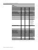
C-12 1734-POINT I/O Module/RSLogix 5000 Controller Tag Reference
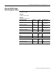
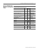
1734-IE2V
2 Channel Analog Voltage Input
Configuration Data Data Type Default
Value
Valid Data Values
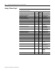
Low Engineering Channel 0 INT 0 -32,768 to 32,767
High Engineering Channel 0 INT 10,000 -32,768 to 32,767
Digital Filter Channel 0 INT 0 0 to 10,000 ms
Low Alarm Limit Channel 0 INT 500 -32,768 to 32,767
High Alarm Limit Channel 0 INT 9,500 -32,768 to 32,767
Low Low Alarm Limit Channel 0 INT 200 -32,768 to 32,767
High High Alarm Limit Channel 0 INT 9,800 -32,768 to 32,767
Range Type Channel 0 SINT 2 0=-10 to +10V
2=0 to 10V
Limit Alarm Latch Channel 0 SINT 0 0=No Latching
1=Alarms Latch
Alarm Disable Channel 0 SINT 0 0=Alarms Enabled
1=Alarms Disabled
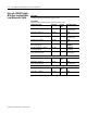
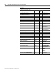
Low Engineering Channel 1 INT 0 -32,768 to 32,767
High Engineering Channel 1 INT 10,000 -32,768 to 32,767
Digital Filter Channel 1 INT 0 0 to 10,000 ms
Low Alarm Limit Channel 1 INT 500 -32,768 to 32,767
High Alarm Limit Channel 1 INT 9,500 -32,768 to 32,767
Low Low Alarm Limit Channel 1 INT 200 -32,768 to 32,767
High High Alarm Limit Channel 1 INT 9,800 -32,768 to 32,767
Range Type Channel 1 SINT 2 0=-10 to +10V
2=0 to 10V
Limit Alarm Latch Channel 1 SINT 0 0=No Latching
1=Alarms Latch
Alarm Disable Channel 1 SINT 0 0=Alarms Enabled
1=Alarms Disabled
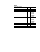
Notch Filter (Channel 0 & 1) SINT 2 1=50Hz
2=60Hz
4=250Hz
6=500Hz
Real Time Sample (Channel 0 & 1) INT 100 0 to 10,000 ms