
User manual


Publication 1734-UM011A-EN-P - February 2004
2-4 Install the 1734-AENT Adapter
7. Set the network address thumbwheel switches to the value used on the
replaced module (see Set the Network Address on page 3--6 in the next
chapter).
8. Insert the end of the terminal block (RTB) opposite the handle into the
base unit. This end has a curved section that engages with the wiring
base.
9. Rotate the terminal block into the wiring base until it locks itself into
place.
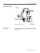
Wiring
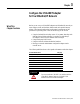
Refer to the illustration to wire the Ethernet adapter
43264
System Power
CHAS GND
C
V
NC
Network Address
Thumbwheels
Field Power
N
C = No Connection
C
HAS GND = Chassis Ground
C
= Common
V
= Supply
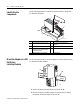
Module Status
Network Activity Status
Network Status
Ethernet RJ-45 Connector
PointBus Status
Module
Status
Network Activity
Status
Network
Status
1734-AENT
PointBus
Status
Field
Power
System
Power
02
0
V dc
NC
C
V
NC
Chas
Gnd
C
V
NC = No Connection C = Common
Chas GND = Chassis Ground V = Supply
0
4
2
6
Chas
Gnd
12/24V dc
This dc supply will be
connected to the
internal power bus.
1
5
3
7
ATTENTION
Do not connect
120/240V ac power
to this supply.