Allen-Bradley Ethernet SLC 500t Processors (Catalog Numbers 1747-L551, -L552, and -L553) Quick Start for Experienced Users
Important User Information Because of the variety of uses for the products described in this publication, those responsible for the application and use of this control equipment must satisfy themselves that all necessary steps have been taken to assure that each application and use meets all performance and safety requirements, including any applicable laws, regulations, codes and standards.
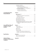
Table of Contents Preface Who Should Use this Manual . . . . . . . . . . . . . . . . . . . . . . . . . . Purpose of This Manual . . . . . . . . . . . . . . . . . . . . . . . . . . . . . . Related Documentation . . . . . . . . . . . . . . . . . . . . . . . . . . . . Conventions Used in this Manual . . . . . . . . . . . . . . . . . . . . . . . Allen-Bradley Support . . . . . . . . . . . . . . . . . . . . . . . . . . . . . . . Local Product Support . . . . . . . . . . . . . . . . . . . . . . . . . . . . .
ii Configuration Via BOOTP . . . . . . . . . . . . . . . . . . . . . . . . . . . . . Using DOS/Windows BOOTP . . . . . . . . . . . . . . . . . . . . . . . . Install the DOS/Windows BOOTP server . . . . . . . . . . . . . . Edit the DOS/Windows BOOTP Configuration File . . . . . . . Run the Boot Server Utility . . . . . . . . . . . . . . . . . . . . . . . . . . Running the DOS-Based Utility . . . . . . . . . . . . . . . . . . . . . Running the Windows-Based Utility . . . . . . . . . . . . . . . . . .
Preface Read this preface to familiarize yourself with the rest of the manual. This preface covers the following topics: • who should use this manual • how to use this manual • related publications • conventions used in this manual • Allen-Bradley support Who Should Use this Manual Use this manual if you are responsible for designing, installing, programming, or troubleshooting control systems that use Allen-Bradley small logic controllers. You should have a basic understanding of SLC 500t products.
P–2 Preface Related Documentation The table below provides a listing of publications that contain important information about Allen-Bradley Small Logic Controllers and their installation and application. You may want to reference them while you are installing the SLC 500 controller. (To obtain a copy of one of these publications, contact your local Allen-Bradley office or distributor.) For Read This Document Document Number 1747-2.
Preface P–3 Conventions Used in this Manual The following conventions are used throughout this manual: • Bulleted lists such as this one provide information, not procedural steps. • Numbered lists provide sequential steps • Italic type is used for emphasis. • Text in this font indicates words or phrases you should type. • Text enclosed “in quotation marks” indicates selections you should make.
P–4 Preface Your Questions or Comments on this Manual If you find a problem with this manual, please notify us using the enclosed Publication Problem Report. If you have any suggestions for how this manual could be made more useful to you, please contact us at the address below: Allen-Bradley Company, Inc. Control and Information Group Technical Communication, Dept. A602V, T122 P.O. Box 2086 Milwaukee, WI 53201-2086 Publication 1747-10.
Chapter 1 SLC 5/05 Ethernet Processor Features This chapter: • describes SLC 5/05 processors and Ethernet communication • describes SLC 5/05 performance considerations • illustrates SLC 5/05 hardware features • explains processor status LED operation • explains keyswitch operation SLC 5/05 Processors and Ethernet Communication Ethernet is a local area network that provides communication between various devices at 10 Mbps.
1–2 SLC 5/05 Ethernet Processor Features Passthru Feature SLC 5/05 (1747-OS501, FRN 3) processors support RS232-to-Ethernet channel-to-channel passthru. See Chapter 5 for more information on using the new passthru feature.
SLC 5/05 Ethernet Processor Features Processor Status LED Operation The table below provides a general explanation of the processor status LEDs. Processor LED RUN (Color: green) FLT (Color: red) BATT (Color: red) FORCE (Color: amber) ENET Channel 1 (Color: green or red) RS232 Channel 0 (Color: green) 1–3 When It Is Indicates that On (steadily) The processor is in Run mode. Flashing (during operation) The processor is transferring a program from RAM to the memory module.
1–4 SLC 5/05 Ethernet Processor Features Keyswitch Operation The processors include a 3-position keyswitch on the front panel that lets you choose from three modes of operation: Run, Program, and Remote. You can remove the key in any of the three positions. ! ATTENTION: Depending on the size of your user program, the processor can take up to 2.5 seconds to change modes when you change the position of the keyswitch from RUN to PROG or to REM.
Chapter 2 Setting Up the SLC and PC Hardware This chapter tells you: • what tools and equipment you need • how to install and wire your power supply • how to install and apply power to your processor • how to configure the SLC 5/05 processor to communicate on the Ethernet network Required Tools and Equipment Have the following tools and equipment ready: • a medium blade screwdriver • programming equipment • a 1747-CP3 programmer cable, a 10Base-T Ethernet PC card and a 10Base-T Ethernet hub Install the
2–2 Setting Up the SLC and PC Hardware 2. Fasten the power supply to the chassis. Use these screws to fasten the power supply to the chassis. 3. Make jumper selection for 120/240V ac on 1746-P1, 1746-P2, and 1746-P4 Power Supplies. Place the input voltage jumper to match the input voltage. This does not apply to the 1746-P3 or 1746-P5, which do not have jumpers. ATTENTION: Set the input jumper before applying power.
Setting Up the SLC and PC Hardware 2–3 5. Connect incoming power, as shown in the following diagrams.
2–4 Setting Up the SLC and PC Hardware Apply Power to the Processor Follow the steps below: 1. Energize the chassis power supply. 2. Check the chassis power supply and processor LEDs. The power LED on the power supply should be on and the fault LED on the processor should be flashing. Power supply and LED Indicators POWER RUN FLT BATT FORCE Indicates the LED is OFF. ENET Indicates the LED is ON. RS232 Indicates the LED is FLASHING. Status of LED does not matter.
Setting Up the SLC and PC Hardware 2–5 Ethernet Channel 1 8-Pin 10Base-T Connector The Ethernet connector is an RJ45, 10Base-T connector. The pin-out for the connector is shown below: Pin Pin Name 1 TD+ 2 TD– 3 RD+ 4 not used by 10BASE-T 5 not used by 10BASE-T 6 RD– 7 not used by 10BASE-T 8 not used by 10BASE-T When to use straight-through and cross-over pin-out: • SLC 5/05 Ethernet port to 10Base-T Ethernet hub cables utilize a straight-through pin-out (1-1, 2-2, 3-3, 6-6).
2–6 Setting Up the SLC and PC Hardware Publication 1747-10.
3 Chapter Configuring the Ethernet Channel for Local Communication This chapter: • describes the configuration methods and configuration parameters • explains how to configure the Ethernet channel using RSLogix Programming Software • explains how to configure the Ethernet channel via BOOTP Configuration Methods Parameter There are two ways to configure the SLC 5/05 Ethernet channel 1.
3–2 Configuring the Ethernet Channel for Local Communication Configuration Using RSLogix500 Programming Software The following step-by-step procedure shows how to set up the SLC 5/05 and establish local communication on an Ethernet network. You need to assign a unique IP address for your processor. This procedure also shows how to create a ladder program for an SLC 5/05 processor and download it via the RS232 COM port on your computer to channel 0 (RS232) on the SLC 5/05.
Configuring the Ethernet Channel for Local Communication 3–3 If you do not use “Auto-Configure”, you must enter the channel 0 default parameters as follows: • • • • • • Device Type: SLC-CH0 Baud Rate: 19200 Parity: None Error Checking: CRC Stop Bits: 1 Protocol: Full Duplex When finished, click “OK”. “AB_DF1-1 DH485 Sta:0 COMn: RUNNING” is added to the list of configured drivers (where n = the number of the COM port you selected). Minimize the RSLinx window. 4.
3–4 Configuring the Ethernet Channel for Local Communication Automatically – In the “I/O Configuration” window, click on “Read I/O Config”. The “Read I/O Configuration from Online Processor” pop-up appears. Select “AB_DF1–1” as the driver and click on the “Read I/O Config” button. Your chassis and I/O configuration updates automatically. Close this window. 10.Using the list on the left side of the screen, double-click on “Channel Configuration” under the “Controller” category. 11.
Configuring the Ethernet Channel for Local Communication 3–5 Create Program and Configure Comms Drivers 1. You are now ready to create your ladder logic. An example is shown below. In this example, there are two SLC 5/05 processors. The MSG instruction from the first processor reads the seconds value of the Real Time Clock (S:42) from the second processor and constantly places the value in the first processor’s file at N7:60. Add the MSG rung to the ladder.
3–6 Configuring the Ethernet Channel for Local Communication Ethernet – In the “Configure Drivers” window, select “Ethernet to PLC-5 or 5820-EI” and click on the “Add New” box. The “Configure Ethernet-to-AB Communications” window appears. Enter the IP address for your SLC 5/05 processor beginning with node 1 under “Current Mappings”. Use the “IP Address or hostname” box to enter the address and click “Accept”. After entering the IP address, click “OK”.
Configuring the Ethernet Channel for Local Communication 3–7 Switch to the Ethernet Network and Go ONLINE 1. Connect your computer and your SLC 5/05 processor to any standard Ethernet hub. You need an Ethernet communication card to connect your PC to the Ethernet hub. 2. In RSLogix, click on the “Comms” pull-down menu and select “System Comms”. In the “System Options” window, change the “Driver” to “AB_ETH-1” and “Apply”. Click on “Who Active”. 3.
3–8 Configuring the Ethernet Channel for Local Communication The host system’s BOOTP configuration file must be updated to service requests from SLC 5/05 processors. The following parameters must be configurable: Parameter Description IP Address A unique IP Address for the SLC 5/05 processor. Subnet Mask Specifies the net and local subnet mask as per the standard on subnetting RFC 950, Internet Standard Subnetting Procedure.
Configuring the Ethernet Channel for Local Communication 3–9 Install the DOS/Windows BOOTP server To install the DOS BOOTP server: 1. Change the directory to the drive containing the BOOTP utility. 2. Type install, and press [Enter]. 3. The software is installed in C:\ABIC\BIN. Put this directory in the path statement of your AUTOEXEC.BAT file. Edit the DOS/Windows BOOTP Configuration File The boot-server configuration file, BOOTPTAB, is located in the C:\ABIC\BIN directory.
3–10 Configuring the Ethernet Channel for Local Communication C. Replace xxyy with the last four digits of the hardware address. Use only valid hexadecimal digits (0-9, A-F); do not use the hyphens that separate the numbers. (You will find the hardware address on a label affixed to the printed circuit board of the SLC 5/05 processor. Note: See page 1–2 for an illustration showing the location of the hardware address.) 4. Save, close, and make a backup copy of this file.
Configuring the Ethernet Channel for Local Communication 3–11 Run the Boot Server Utility You can run either the DOS-based utility or the Windows-based BOOTP utility, but not both. If you have BOOTP enabled and the message BOOTP response not received appears, check the cabling connections and the BOOTP server system. If you’re using this platform then invoke this executable DOS-based Windows from the See page DTLBOOTD.EXE DOS command line (specify optional parameters if necessary) 3–11 DTLBOOTW.
3–12 Configuring the Ethernet Channel for Local Communication 2. Apply power to all chassis containing SLC 5/05 processors. At power-up, each SLC 5/05 processor broadcasts a BOOTP request if BOOTP was enabled at the channel 1 configuration screen. The Ethernet boot server compares the hardware address with those listed in BOOTPTAB and responds by sending the corresponding IP address and other configuration data to the client via a BOOTP reply.
Chapter 4 Communicating on the Ethernet Network This chapter: • describes how Ethernet connections are established • provides information on MSG instruction parameters, interpreting MSG error codes, and interpreting Ethernet status data • explains how to use advanced Ethernet functions Ethernet Connections TCP/IP is the mechanism used to transport Ethernet messages. On top of TCP, the Client/Server Protocol is required to establish connections and to send the MSG commands.
4–2 Communicating on the Ethernet Network MSG Instruction The SLC 5/05 processors use the MSG instruction to communicate over the Ethernet network. The table below describes MSG instruction parameters for Ethernet.
Communicating on the Ethernet Network 4–3 Control Block Layouts The SLC 5/05 MSG control block length varies with the type of communication and with the addressing you use. Control block layouts are shown for: • SLC 5/05 Channel 1 (Ethernet port) MSG Control Block without Logical ASCII Addressing • SLC 5/05 Channel 1 (Ethernet port) MSG Control Block with Logical ASCII Addressing valid for PLC-5 typed read or write only The AO bit (word 12, bit 15) is used for PLC-5 type reads and writes.
4–4 Communicating on the Ethernet Network MSG Instruction Control Block The following are MSG control blocks, without and with logical ASCII addressing. The length of the control block without logical ASCII addressing is 51 words. With logical ASCII addressing, the length of the control block is 93 words.
Communicating on the Ethernet Network 4–5 SLC 5/05 Channel 1 (Ethernet port) MSG Control Block with Logical ASCII Addressing valid for PLC-5 typed read or write only WORD 0 1 2 3 4 5 6 7 8 9 10 11 12 13 14 15 16 55 56 57 76 77 78–92 15 14 13 12 11 10 09 08 07 06 05 04 03 02 EN ST DN ER CO EW NR TO Error Code Reserved (Target Node Not Used) Number of Elements Not Used File Type (based on local source or destination address) Not Used Not Used Reserved (Internal Messaging Bits) Message Timer Preset Messa
4–6 Communicating on the Ethernet Network Interpreting MSG Error Codes When the processor detects an error during the transfer of message data, the processor sets the .ER bit and enters an error code that you can monitor from your programming software. Error Code 02H 03H Description of Error Condition Target node is busy. The MSG instruction automatically reloads. If other messages are waiting, the message is placed at the bottom of the stack. Target node cannot respond because message is too large.
Communicating on the Ethernet Network Error Code 4–7 Description of Error Condition D4H Connection not completed before user-specified timeout D5H Connection timed out by the network D7H Connection refused by destination host D8H Connection was broken D9H Reply not received before user-specified timeout DAH No network buffer space available E1H PCCC Description: Illegal Address format, a field has an illegal value. E2H PCCC Description: Illegal Address format, not enough fields specified.
4–8 Communicating on the Ethernet Network Interpreting Ethernet Status Data Publication 1747-10.4 Monitor the status of SLC 5/05 processors by accessing the Ethernet channel 1 status screen of your programming software.
Communicating on the Ethernet Network 4–9 The diagnostic counter data displayed is stored in the diagnostic file defined on the Ethernet channel 1 configuration screen. Status field: Commands Replies Ethernet Bytes: Displays the number of: sent 0-3 Commands sent by the channel. received 4-7 Commands received by the channel. sent 8-11 Replies sent by the channel. received 12-15 Replies received by the channel. sent with error 16-19 Replies containing errors sent by the channel.
4–10 Communicating on the Ethernet Network Using Subnet Masks and Gateways Configure subnet masks and gateways using the Ethernet channel 1 configuration screen: Important: If BOOTP is enabled, you can’t change any of the advanced Ethernet communications characteristics.
Communicating on the Ethernet Network 4–11 Manually Configuring Channel 1 for Processors on Subnets If you are manually configuring channel 1 for a processor located on a subnet, deselect the “BOOTP Enable” option by clicking on the checked box. See the table below to configure the subnet mask and gateway address fields for each processor via your programming software.
4–12 Communicating on the Ethernet Network Using BOOTP to Configure Channel 1 for Processors on Subnets Configure the BOOTPTAB file according to the subnet mask and gateway address for each SLC 5/05 processor on the link. See the example below and the corresponding BOOTPTAB file on the next page. Important: Because BOOTP requests are seen only on the local subnet, each subnet needs its own BOOTP server and BOOTPTAB file.
Communicating on the Ethernet Network 4–13 The BOOTPTAB files that correspond to this example look like: # # # # # # # Legend: gw –– gateways ha –– hardware address ht –– hardware type ip –– host IP address sm –– subnet mask vm –– BOOTP vendor extensions format tc –– template host #Default string for each type of Ethernet client defaults5E: ht=1:vm=rfc1048:sm=255.255.255.0 #Entries for SLC 5/05 processors: iota1:\ tc=defaults5E:\ gw=130.151.194.1:\ ha=0000BC1D1234:/ ip=130.151.194.
4–14 Communicating on the Ethernet Network Publication 1747-10.
Chapter 5 Using RS232 to Ethernet Channel to Channel Passthru This chapter contains information about the new passthru feature on SLC 5/05 (1747-OS501, FRN 3) processors, including: • • • • Passthru Feature Updated status file information Error code information An example of DF1-to-Ethernet and Ethernet-to-DF1 routing An example of DH485-to-Ethernet and Ethernet-to-DH485 routing This feature permits an SLC 5/05 processor to act as a bridge, allowing communication data packets to be passed between th
5–2 Using RS232-to-Ethernet Channel-to-Channel Passthru Status File Bits Two status file bits control whether or not the passthru function is enabled. Their SLC 5/05 functions are described in the table below. Address S:34/0 Classification Dynamic Configuration Description DH485 to Ethernet Passthru Disable Bit (SLC 5/05, OS501 or later) When this bit is set, passthru is disabled. When it is reset, the processor allows packets to be passed from one channel to the other.
Using RS232-to-Ethernet Channel-to-Channel Passthru Passthru Examples 5–3 The IP Addresses used in the following illustrations are for example purposes only. Contact your system administrator for IP addresses unique to your network. Example 1: DF1-to-Ethernet and Ethernet-to-DF1 In the following diagram, the SLC 5/03 sends a local message via DF1 to the SLC 5/05 #1. The SLC 5/05 #1 acts as a bridge, sending the message out via Ethernet to the SLC 5/05 #2, whose address is stored in the routing table.
5–4 Using RS232-to-Ethernet Channel-to-Channel Passthru SLC 5/03 Using DF1 The message ladder logic, message setup, and channel configurations for the SLC 5/03 using DF1 are shown below. SLC 5/03 Message Ladder Logic SLC 5/03 Message Setup • Channel is set to zero for DF1 full-duplex protocol. • Target Node is the station address in the SLC 5/05 #1 routing table where the IP address for SLC 5/05 #2 is stored.
Using RS232-to-Ethernet Channel-to-Channel Passthru 5–5 SLC 5/03 Channel Configurations • Channel 0 Driver is set to DF1 Full Duplex. • Source ID is the address of the sender of the message. It can be any number from 0 to 254. SLC 5/05 #1 Bridge Ladder logic is not required for the SLC 5/05 which acts as the bridge from DF1-to-Ethernet. However, you must set up a passthru routing table when configuring the bridge. The channel configuration is shown below, followed by the routing table on page 5–7.
5–6 Using RS232-to-Ethernet Channel-to-Channel Passthru Important: Publication 1747-10.4 Channel 0 Source ID must be set to 0 when SLC 5/05 #1 is used as the bridge between DF1 full-duplex and Ethernet.
Using RS232-to-Ethernet Channel-to-Channel Passthru 5–7 Passthru Routing Table The passthru routing table is located under the channel configuration selection in RSLogix 500 Programming Software. If a Passthru Routing Table File number was entered in the General Tab in the Channel Configuration dialog box, click on the + in front of “Channel Configuration” to reveal the routing table selection. Double-click on “Routing Table” to view and modify the passthru routing table.
5–8 Using RS232-to-Ethernet Channel-to-Channel Passthru SLC 5/05 #2 Using Ethernet For DF1-to-Ethernet passthru, SLC 5/05 #2 is the receiver and does not require message ladder logic, only a correct IP address and proper channel configuration. For Ethernet-to-DF1 passthru, SLC 5/05 #2 is the initiator and must have ladder logic. The program below shows how the SLC 5/05 #2 processor can initiate a message to the SLC 5/03 via the SLC 5/05 #1 bridge.
Using RS232-to-Ethernet Channel-to-Channel Passthru 5–9 SLC 5/05 #2 Message Setup • Channel is set to 1 for Ethernet. • Message Timeout for any Ethernet MSG cannot be modified in the Ethernet Message Setup dialog box. It is assigned by the processor, and is determined by adding the Channel 1 MSG Connection Timeout to the MSG Reply Timeout, then adding 5 seconds. This value can be modified by changing one or both of the timeout values in the channel 1 channel configuration screen.
5–10 Using RS232-to-Ethernet Channel-to-Channel Passthru SLC 5/05 #2 Channel Configuration Note: Publication 1747-10.4 A zero in the Passthru Routing Table File indicates that this processor is not being used as a bridge. A passthru routing table will not be created.
Using RS232-to-Ethernet Channel-to-Channel Passthru 5–11 Example 2: DH485-to-Ethernet and Ethernet-to-DH485 In the following diagram, the SLC 5/03 uses DH485 protocol to send a remote message to SLC 5/05 #1. The SLC 5/05 #1 passes the message through to SLC 5/05 #2 via Ethernet. The SLC 5/05 #2 can also send a message to the SLC 5/03 via the SLC5/05 #1 bridge. The SLC 5/05 #1 processor routes the message to the SLC 5/03 via DH485.
5–12 Using RS232-to-Ethernet Channel-to-Channel Passthru SLC 5/03 Ladder Logic SLC 5/03 Message Setup • Channel is set to one, the DH485 default. • Target Node is the address in the SLC 5/05 #1 routing table where the IP address for SLC 5/05 #2 is stored. • The Message Timeout must be at least as long as the SLC 5/05 timeout for Ethernet connection. The SLC 5/05 default timeout is 23 seconds. • The Remote Bridge Link ID is the Link ID of Channel 1 of the SLC 5/05 #1 bridge.
Using RS232-to-Ethernet Channel-to-Channel Passthru 5–13 SLC 5/03 Channel Configuration • Channel 1 Driver is set to DH485. • Node Address is the address of the SLC 5/03 processor. Publication 1747-10.
5–14 Using RS232-to-Ethernet Channel-to-Channel Passthru SLC 5/05 #1 Bridge Ladder logic is not required for the SLC 5/05 which acts as a bridge from DH485-to-Ethernet. However, you must set up a passthru routing table file when configuring the bridge. The channel configuration is shown below, along with the routing table. SLC 5/05 #1 Bridge Channel Configuration Publication 1747-10.
Using RS232-to-Ethernet Channel-to-Channel Passthru 5–15 Publication 1747-10.
5–16 Using RS232-to-Ethernet Channel-to-Channel Passthru Passthru Routing Table The passthru routing table is located under the channel configuration selection in RSLogix500 Programming Software. If a Passthru Routing Table File number was entered in the General Tab in the Channel Configuration dialog box, click on the + in front of “Channel Configuration” to reveal the routing table selection. Double-click on “Routing Table” to view and modify the routing table. Important: Publication 1747-10.
Using RS232-to-Ethernet Channel-to-Channel Passthru 5–17 SLC 5/05 # 2 Using Ethernet For DH485-to-Ethernet passthru, SLC 5/05 #2 is the receiver and does not require message ladder logic, only a correct IP address and proper channel configuration. For Ethernet-to-DH485 passthru, SLC 5/05 #2 is the initiator and must have ladder logic to send a message to SLC 5/03 via the SLC 5/05 #1 bridge. The SLC 5/05 remote message ladder logic, message setup, and channel configurations are shown below.
5–18 Using RS232-to-Ethernet Channel-to-Channel Passthru SLC 5/05 #2 Message Setup • Channel is set to one for Ethernet. • Target Node is the DH485 node address of the SLC 5/03 • • • • Publication 1747-10.4 destination processor. Message Timeout for any Ethernet MSG cannot be modified in the Ethernet Message Setup dialog box. It is assigned by the processor, and is determined by adding the Channel 1 MSG Connection Timeout to the MSG Reply Timeout, then adding 5 seconds.
Using RS232-to-Ethernet Channel-to-Channel Passthru 5–19 SLC 5/05 #2 Channel Configuration Note: A zero in the Passthru Routing Table File indicates that this processor is not being used as a bridge. A passthru routing table will not be created. Publication 1747-10.
5–20 Using RS232-to-Ethernet Channel-to-Channel Passthru Publication 1747-10.
A Appendix Specifications System Test General Specifications Description The table below lists SLC 500 system test specifications. Specification Industry Standard Operating: 0°C to +60°C (32°F to 140°F) Not Applicable Storage: –40°C to +85°C (–40°F to 185°F) Not Applicable 5 to 95% without condensation Not Applicable Operating: 1.0G at 5 to 2000 Hz Not Applicable Non-operating: 2.5Gs at 5 to 2000 Hz Not Applicable Operating: 30.0Gs (3 pulses, 11 ms) Not Applicable Operating: 10.
Variable Content TTL:Chap Is Linked To HD:Running A–2 Processor General Specifications The table below describes the general specifications for the SLC 5/05 processors. Specification 1747-L551 1747-L552 Memory Size 16K Words I/O Capacity up to 4096 inputs and 4096 outputs Maximum Chassis/Slots 3/30 Standard RAM Lithium Battery (2 years) Memory Back-up Options Flash EPROM LED Indicators Run, CPU Fault, Battery Low, Forced I/O, Ethernet, RS-232 Typical Scan Time ➀ 32K Words 0.
Appendix B (Optional) Return Processor to Initial Factory Conditions Use this procedure if the communication channels are shut down because they were configured to be shut down, or if you absolutely cannot establish communications with the processor. ! ATTENTION: If you return the processor to the initial factory conditions, the user program and communication configurations are returned to their default settings. 1. Remove power from the SLC 500 power supply. 2. Remove the processor from the chassis.
B–2 Variable Content TTL:Chap Is Linked To HD:Running Publication 1747-10.
Publication 1747-10.
Allen-Bradley, a Rockwell Automation Business, has been helping its customers improve productivity and quality for more than 90 years. We design, manufacture and support a broad range of automation products worldwide. They include logic processors, power and motion control devices, operator interfaces, sensors and a variety of software. Rockwell is one of the world’s leading technology companies. Worldwide representation.