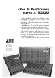
Allen & Heath’s new stereo 21 SERIES Allen & Heath proudly unveil their exciting new range of compact stereo mixers - the 21 SERIES. Stylish in looks and superb in performance, these four models offer outstanding value for money. Available in 6, 12, 18 and 24 input versions, the 21 SERIES boasts the useful feature of a separate mono output derived from the main stereo mix.
AUDIO QUALITY Advanced low-noise circuitry boasts a high slew rate of 13 V/uS, permitting faithful reproduction of transient information. Each mixer is supplied complete with its own external power supply to ensure that hum fields are kept to a minimum. Phantom power is available as an optional extra. As the comprehensive PFL system overrides all monitor outputs and metering, easy checks may be made on all incoming and outgoing signals.
STEREO 21 SERIES OWNER'S HANDBOOK
SPECIFICATION: Construction: steel main panel and covers, hard stove enamel paint finish with epoxy ink screenprinted legend. Semimodular electronic printed circuit assemblies. IC op-amp and discrete transistor audio system of transformerless design. Weight Height Depth 9.5kg 476 90mm (14.0) (160) (620) 1221 476 90 14.0 (19.0) (160) (620) (710) 1821 889 476 90 18.5 (24.0) (160) (620) (930) 2421 1105 476 90 23.5 (29.0) (160) (1160) (620) bracketed figures = in shipping carton.
2 GENERAL All Outputs: Normal Operating Level = +4dBv Maximum Output Level = +2ldBv 20Hz to 20kHz Output Impedance = 30ohms all outputs are protected against damage from accidental short circuits. Maximum Gain From Channel Input to Stereo Output: = +70dB Frequency Response: Channel Input to Stereo Output = 30Hz to 30kHz +/-1dB Equaliser Characteristics: HF = 15dB continuously variable at 10kHz MID = +/-13dB continuously variable at any frequency between 400Hz and 6kHz. Q factor = 1.
3 Channel Inputs: XLR sockets. Electronically balanced suitable for safe connection of external phantom power supply of up to 48VDC.
4 Monitor Output: stereo 1/4" jack socket tip = left ring = right outer = earth Normal Operating Level = +4dBv Maximum Gain = +10dB Headphones Output: stereo 1/4" jack socket capable of driving stereo phones of 4ohms to 600ohms impedance Tie Buss Svstem: Stereo Input - stereo 1/4" jack socket tip = left ring = right outer = earth Gain to Stereo Output = 0dB Stereo Output - stereo 1/4" jack socket Normal Operating Level = +4dBv Mono Input - mono 1/4" jack socket Gain to Mono Output = 0dB Auxilliary Input
5 PANEL CONTROLS Input Channel Place the mixer in front of you and familiarise yourself with the various functions of the panel controls. Starting at the top of an input channel the first control is: a) GAIN This control adjusts the sensitivity of the first amplification stage of the microphone/line input. Use this in conjunction with the PFL function, as described in the OPERATION section, to find the correct setting.
6 h) ECHO Can be used in a similar way to the above control, except that it is wired post-fader and the feed to an external effects device will reduce as the channel fader is lowered. Use in conjunction with the echo master (see OUTPUT SECTION) to set correct operating level. i) PAN Use to position the signal anywhere between left and right in the stereo mix. PFL is an abbreviation for Pre-Fader-Listen.
7 OUTPUT SECTION a) VU METERS The VU meters can read any one of 4 signal sources: i) PFL: when any PFL button is pressed on the mixer, an LED just above the right VU meter will illuminate (as a reminder), and the meters will follow the selected PFL level (in mono). ii) The output signal level of a stereo tape recorder when TAPE is selected in the monitor section. iii) The main stereo mix output from the mixer when STEREO is selected in the monitor section.
8 f) MONO MASTER FADER Controls the output level of the mono mix. This mix is a mono sum of the main stereo output, is derived after the left/right master faders, and therefore depends upon their position for output level. PFL select is available to check the signal supplying the mono output for level and quality. g) MONITOR SECTION This section selects the signals available for headphone monitoring via the top panel socket and/or for control room monitoring via the monitor output socket on the rear.
9 OPERATION Objective: To preserve the quality of the original sound. Assisted by: Level controls, gain controls, mixer meters, peak indicators, tape meters and tape. Level control - Operator control changing the signal level between sections of a console system, often a passive device (fader, pot). Gain control - Operator control changing the shift in signal level between the input and output of an amplifier in one section of a console system.
10 1) The audio amplifier system noise is allowed to be greater than the ambient (background) noise of the original sound. Details of the quieter sections of programme are lost. 2) The audio amplifier system maximum signal level for faithful reproduction is exceeded by the original sound. Details of the louder sections of the programme are lost and the audio system adds masking distortions generated by overload of the amplifiers.
11 clipped signal reading is the overload margin of the system. Going the other way: Reset the piano mic 20 feet back. Back at the console reset the controls to get 0VU again on loud phrases and reset the monitor level for a true volume in the control room. It probably sounds OK. Now ask the piano player to give you his favourite quiet subtle number. Reset the mic gain for 0VU on the PFL meter.
12 All that has been said about the balance between added noise and added clipping distortion applies to the other parts of a console system not just the preamp. This is why the faders show a zero '0' calibration point from which to work as a start for level balancing and why PFL switches are provided on the output faders as well as on input channels.
13 inputs for tape signals are preset to a standard signal level (0VU = +4dBm). There are however three standard signal levels that different tape decks may produce: 0VU = +4dBm (1.23V RMS) 0VU = 0dBm (0.775V RMS) 0VU = -10dBV (0.3lV RMS). Consult the page of this book "Tape deck interface" for guidance on obtaining the best from the tapedeck - console system. Your Allen and Heath console is engineered to work perfectly with all three standard level systems.
14 TAPE DECK INTERFACE Your 21 series mixer is supplied with output levels and tape return It is a very simple operation levels set for 0VU on meters = 4dBm. to change operating levels to suit tape machines that require a lower operating standard. The output levels from the stereo and mono outputs and also the input level to the stereo tape input can all be independantly adjusted. Stand the mixer on rear panel, ensuring safe and adequate support. Remove bottom panel using POZI 2 screwdriver.