
User's Manual
ZEDi-8 8 Channel Live + Recording Mixer User Guide
Thank you for purchasing this Allen & Heath ZEDi-8.
We recommend that you read all of this user guide to get the best from your mixer and after
reading, please keep this safe for future reference.
Included in this package is:
ZEDi-8 Mixer
IEC C5 Mains Power Cable. Please check correct mains plug is fitted for your country.
This User Guide!
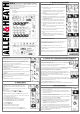
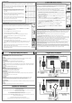
1.3 MASTER SECTION
1. MAIN OUT L & R are line level outputs for the main stereo mix using standard XLR
output connectors and are impedance balanced for rejection of unwanted interference.
2. MAIN OUT = MONITORS switches the PFL signal to the MAIN OUT as well as the
PHONES output for flexible monitoring of input signals through your speakers.
This is mainly for studio control room monitoring applications.
3. 48V switches industry standard 48V (phantom power) to both microphone inputs for
use with condenser microphones.
4. POWER LED indicates that the mixer is switched on.
5. LR Meters display the level of the MAIN MIX or the mono PFL signal if activated by
any of the PFL switches.
6. MAIN MIX is the master volume control for the main stereo mix.
7. PFL (Pre-Fade Listen) LED indicates when a PFL switch has been pressed on one of
the channels.
8. PHONES level controls the volume of signal to the PHONES output.
Warning! To avoid damage to your hearing do not operate headphones or sound system
at excessively high volume. Continued exposure to high volume sound can cause frequency
selective or wide range hearing loss!
!
9. PHONES output uses a standard 1/4” (6.25mm) jack socket.
2.1 “Zeroing”
It’s good practice to “zero” your mixer and turn down relevant channels before
connecting any devices as this prevents potential damage to speakers or other
equipment.
Follow these steps to make sure you’re safe and you avoid thumps and bangs when
plugging equipment in.
Speakers should always be switched ON LAST and OFF FIRST!
1. Make sure the power switch on the rear of the mixer is set to “OFF”
2. Connect the AC Mains Lead provided to the AC MAINS IN socket on the rear of the
mixer.
Check that the correct mains plug is fitted for your country and plug the AC Mains Lead
into a standard household mains socket.
3. Turn channel Gain controls all the way down (left).
4. Make sure Instrument, HPF, PFL and 48V switches are not pressed in.
5. Set all channel EQ and PAN controls to the centre position marked “▼”
6. Turn all FX send, AUX send and MIX controls all the way down (left).
7. Lower the MAIN MIX fader to “∞”.
8. Turn down the PHONES level.
9. Double check speakers or amplifiers are switched off!
10. Connect speakers, instruments and other equipment.
11. Switch on instruments and other equipment, then mixer, THEN speakers !
Speaker or amp volumes should be set according to manufacturer guidelines. !
2. Good practice
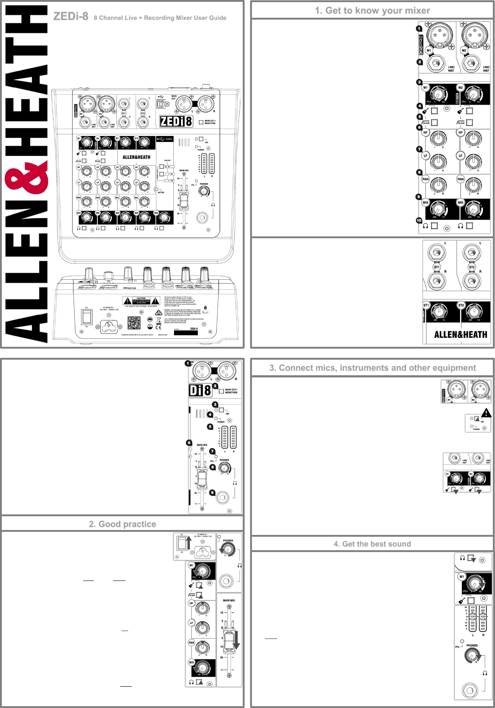
3.1 Connecting Microphones
Dynamic or condenser microphones and DI boxes should be connected to the Mic Input Socket
using a balanced XLR Microphone cable.
If you‘re using a condenser microphone, it will require 48V Phantom Power to work.
Some active DI boxes may also require phantom power.
Avoid ‘hot plugging’ when connecting any equipment and make sure AUX MASTER and MAIN MIX controls
are turned down before 48V is switched on as this as may cause loud thumps and bangs!
3.2 Connecting Instruments and Line-Level Equipment
High-Impedance (Hi-Z) instruments such as electro-acoustic guitars, basses and other Direct
Input instruments should be connected to Line / Inst Inputs on channels M1 & M2 using a jack to
jack instrument cable, and do not require an additional DI box or preamp.
The Instrument switch must be activated to match extremely high impedance signals (10MΩ)
from instrument pickups.
Line level instruments such as keyboards, synthesizers, drum machines or equipment such as
external effect processors can be connected to Line / Inst Inputs on channels M1 & M2, and LINE inputs on M3 & M4 for
mono sources or ST1 & ST2 for stereo sources.
For channels M3 & M4 the LINE/PAD switch must be activated.
Follow the application examples in Section 7. for connecting devices to relevant input and outputs.
4.1 Gain Structure
1. Once you’ve connected your instruments and equipment you will need to set input levels before
you can mix the signals together.
2. Gain structure is important to get the maximum signal level without undesirable distortion.
Setting gain properly helps to optimise signal quality and ensure that the signal to noise ratio
remains as low as possible.
3. If you‘re using a microphone make sure the mic is placed at an appropriate distance to the sound
source. (Close for quiet sources, further away for louder).
4. Press the PFL switch on the corresponding channel. This will allow you to hear the pre-fader
input signal and will show the signal level on the LR Meters.
5. Sing, talk or play your instrument at a typical level of loudness.
6. Slowly raise the Gain Control on the corresponding channel until you see a good signal level in
the LR Meters. Maximum peaks between “0” and “+6” on the meters are a good indicator.
7. Connect professional monitoring headphones to the Phones output and turn up the
PHONES level to a safe listening volume.!
8. If the signal sounds undesirably distorted at a low signal level, enable any pad switch on the
microphone, or move the microphone further away from the source and repeat the process.
Once you’re happy with the input signal level, you may wish to use lo-cut (Hi-pass Filter) and the EQ
to enhance intelligibility or to remove unwanted frequencies, and improve the tonal balance of the
source sound, so keep the channel PFL switch enabled for now!
Section 4. continued overleaf...
4. Get the best sound
3. Connect mics, instruments and other equipment
1. Get to know your mixer
1.1 MONO INPUT CHANNELS (M)
1. Mic Input Socket uses a standard 3-Pin XLR socket for connecting dynamic
or condenser microphones.
2. Line / Inst Input Socket uses a standard 1/4” (6.25mm) Jack socket for
connecting balanced or unbalanced signals such as guitars and other
instruments.
3. Gain Control adjusts the gain of the input preamplifier to drive the
source signal level. Gain ranges from 5dB to 60dB.
4. Instrument activates the Line / Inst input circuit for electro-acoustic and
electric guitars, basses and other Direct Input instruments. When activated
the Mic Input Socket is disabled.
5. lo-cut (Hi-Pass Filter) is used for reducing Low Frequency noise such as
handling noise, popping, rumble and proximity effect in microphone signals.
6. HF EQ (High Frequency) equaliser affects treble frequencies in the
signal for adding “brightness” and “definition” or for reducing “hiss” and
“harshness”.
7. LF EQ (Low Frequency) equaliser affects bass frequencies in the signal
to cover “boom” and “sub-bass” frequencies.
8. PAN adjusts signal from a mono input channel between the left and
right busses and subsequently the main outputs.
9. MIX rotary fader controls the amount of signal to the left and right
busses.
10. Pre-Fade Listen (PFL) switches the channel input signal to the
headphones for checking before adding it to Mix. The PFL signal is taken
after the EQ but before the MIX control.
1.2 STEREO INPUT CHANNELS (ST)
ST1 and ST2 Inputs use standard 1/4” (6.25mm) Jack sockets for balanced or
unbalanced line level stereo sources such as professional keyboards, drum
machines and other pro audio equipment.
ST1 and ST2 Gain Control adjusts the input level to the channel.
HF and LF EQ are the same for ST1 & ST2 as they are for M1 & M2 and are set
at the same frequencies.
BAL adjusts the relative level between the left and right stereo signals as they
are sent to the left and right busses and subsequently the main outputs.