Balanced Analogue Interface Module USER GUIDE Publication AP9109
Limited One Year Manufacturers Warranty This product is warranted to be free from defects in materials or workmanship for period of one year from the date of purchase by the original owner. To ensure a high level of performance and reliability for which this equipment has been designed and manufactured, read this User Guide before operating. In the event of a failure, notify and return the defective unit to the place of purchase.
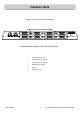
PACKED ITEMS Check that you have received the following: ALLEN&HEATH INPUTS 1-8 MIDI OUT 9-16 1-8 25-32 17-24 OUTPUTS 9-16 BALANCED ANALOGUE I/O MODULE MIDI IN 17-24 25-32 GS-R24 BALANCED ANALOGUE INTERFACE MODULE Also Packed in the box Allen & Heath • Safety Instructions—English • Safety Instructions—French • Addendum note ROHS • Sticker • This User Guide 4 GS_R24 Balanced Analogue Module User Guide
CONTENTS Thank you for purchasing your Allen & Heath GS-R24 Analogue interface module. To ensure that you get the maximum benefit from the unit please spare a few minutes familiarizing yourself with the features and setup procedures outlined in this user guide. For further information please refer to the additional information available on our web site, or contact our technical support team. http://www.allen-heath.
GS-R24 ANALOGUE MODULE SPECIFICATIONS General Specifications Number of audio channels Output 32 Number of audio channels Input 32 Nominal Signal Level +4dBu Balanced Analogue signal connector type 25 pin D-Sub Female (TASCAM standard pinout) MIDI Input 5pin DIN MIDI Output 5pin DIN Headroom Analogue Headroom 21dB Channel Mapping to Interface Console Channels Interface Channels Mono Channels 1-24 1-24 * Stereo Channel 1 25-26 (L-R) Stereo Channel 2 27-28 (L-R) Valve Channel 1 29 Valv
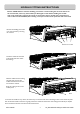
MODULE FITTING INSTRUCTIONS Beware of ESD! Observe anti-static handling precautions—avoid touching the electronic devices on the circuit board, ensure any static build up is discharged to earth before handling the module. This can be achieved by ensuring the console is connected to the psu and the psu is plugged in to a mains outlet but switched OFF, then touching a metal part of the console panel such as a screw head. Remove the blanking panel at the rear of the console by removing the 4 screws.
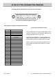
25 PIN D TYPE CONNECTOR PINNING Analogue Input & Output 25 way D connector pin ident. 13 1 25 14 Pin assignment (Input or Output connectors) Connection guidelines & notes IN No.
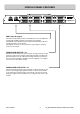
MODULE PANEL FEATURES ALLEN&HEATH 1-8 MIDI OUT INPUTS 9-16 1-8 25-32 17-24 OUTPUTS 9-16 BALANCED ANALOGUE I/O MODULE MIDI IN 17-24 25-32 MIDI Input & Output Standard 5 pin DIN MIDI connectors. The MIDI OUT carries the MIDI data generated by the MIDI controllers and switches on the GS-R24. The MIDI IN is the MIDI data required to illuminate LEDs and provide moving fader information to the console. The MIDI IN connector can also be used for programming the operating firmware in the console.
PRODUCT SUPPORT Investigate ALLEN & HEATH’s other ranges at www.allen-heath.com Large Live Sound mixers — iLive digital, and GL Series Small Format Live Sound mixers — ZED, MixWizards and PA Series DJ products — Xone Series Sound Management Series — iDR Series Registering your product Thank you for buying the Allen & Heath GS-R24 module. We hope that you are happy with it and that you enjoy many years of faithful service with it, and record and mix some great music. Please go to www.allen-heath.