
User Manual


Allen & Heath 24 XB-14 User Guide
9
10
8
11
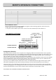
MASTER SECTION
8
9
Main Left & Right meters
12 segment LED meters, peak type response, the “0” position reflects
nominal level at the outputs (+4dBu from the main PGM outputs).
The meters display the signals from the CRM + Phones selector
switches below, or the PFL (pre-fade listen) signal from any selected
channels, which overrides.
48v Phantom Power switch
Press this in to switch 48v Phantom Power to the 4 Mic input xlr
connectors, if any of the microphones attached require power.
Dynamic microphones won’t mind being connected to a phantom
powered input, but care is needed to ensure that 48v is not switched
on if an xlr is used to input a signal from an electronic circuit (ie. An-
other mixer or keyboard).
When switching 48v on or off, or plugging in connectors to
channels with 48v present, it is important (and normal pro-
cedure) to mute the channels. This will avoid loud clicks and
bangs potentially getting through to the amps & speakers
with the possible effect of damaging the speakers, or the au-
dience’s hearing!
10
PFL Active LED
Illuminates red when any one or more PFL (pre-fade listen) switch is
pressed. Indicates that the meters are displaying the PFL signal rather
than the signal from the selected source.
11
CRM + PHONES Source Selector switches
These 4 switches select the signal source for the control room speak-
ers, headphones monitor and the meters. They work on a priority
basis. If they are all up then the post-fade main PGM signals will feed
the monitor circuit, if any of the switches are pressed then the PGM
signal will be replaced. If more than one switch is pressed the switch
nearest the meters will take priority.
The PFL signal will override the selection to the meters and CRM if
activated.
12
GUEST PHONES Source Selector switches
Similar to the CRM + PHONES selection switches, these select the
source for the guest headphones output. The choices are the same as
for the CRM outputs, but a different source can be selected for the
guests to that selected for the operator.
The PFL signal will not be fed to the guest phones outputs unless the
PFL ENABLE TO GUEST switch is pressed. This is an under-panel
switch so it cannot be operated accidentally.
13
CRM Speakers level
Adjusts the level of the signal to the control room speaker outputs
from off (fully attenuated) to unity gain.
13
12
L
+16
-6
-9
-20
-30
-16
-12
-3
0VU
+3
+6
+9
R
PFL ACTIVE
MIN MAX
PHONES
AUX
MIX B
EXT
CRM
SPEAKERS
L
R
48V
INSERT R
MAIN
PHANTOM POWER
ALLEN HEATH
AUX
INSERT L
+16
-6
-9
-20
-30
-16
-12
-3
0VU
+3
+6
+9
CUT SPKS
DIM SPKS
TO MICS
PFL ENABLE
TO GUEST
GUEST PHONES 1
GUEST PHONES 2 CRM PHONES
EXT MON IN
L
R
0
5
10
15
20
MIN MAX
CRM
TALK
TO GUEST
POWER
MIX B OUT
L
R
MIN MAX
LEVEL
MIX B
PGM MIX
FADER
CRM+PHONES
SELECTION
USB
PHONES
MIN MAX
GUEST
GUEST PHONES
SELECTION
MIC FADER UP
=CUT SPKS
MONO
OUT
IN
MON
OUT
&
PGM