ALLEN&HEATH GL2200 Dual Function Audio Mixing Console USER GUIDE PUBLICATION: AP3388
LIMITED ONE YEAR WARRANTY This product has been manufactured in the UK by ALLEN & HEATH and is warranted to be free from defects in materials or workmanship for period of one year from the date of purchase by the original owner. To ensure a high level of performance and reliability for which this equipment has been designed and manufactured, read this User Guide before operating.
CONTENTS CONTENTS ..................................................................................................... 3 INTRODUCTION, SERVICE, SAFETY & PRECAUTIONS .......................................... 4 KEY FEATURES, THE RANGE & OPTIONS ........................................................... 5 CONNECTING POWER TO THE CONSOLE ............................................................ 6-7 EARTHING THE AUDIO SYSTEM .........................................................................
INTRODUCTION The GL2200 continues ALLEN & HEATH’s commitment to provide high quality audio mixing consoles engineered to meet the exacting requirements of today’s audio business. It brings you the latest in high performance technology and offers the reassurance of over two decades of console manufacture and customer support. This user guide presents a quick reference to the function, application and installation of the GL2200.
KEY FEATURES OF THE GL2200 The ALLEN & HEATH GL2200 offers the user the versatility to quickly adapt to the exacting demands of live sound engineering today. The GL2200 is developed from the very successful GL2000 console, which included mode switching to quickly convert the console from Front-of-House to On-stage Monitor operation. In addition, the GL2200 includes 4 subgroups, 6 independent aux sends, stereo mic/line channels, pink noise generator, 1kHz oscillator and lots more.
CONNECTING POWER TO THE CONSOLE Refer to the SAFETY WARNING on page 4 of this User Guide. Read and understand the warnings and instructions printed on the rear panel of the console and printed here. Ensure adequate ventilation around the console. Do not cover the console or position it on soft furnishings during operation. The console must be connected to 0V ground by either the a.c. mains input cable or by the EXTERNAL DC IN cable.
An external DC supply may be used instead of, or together with the internal supply. Use only recommended Allen & Heath power supplies or a supply approved by Allen & Heath. The use of alternative supplies is not recommended and may cause damage. The pin connections for the EXTERNAL DC IN connector are specified below: Pin Voltage Current 1 -16V 1.5A 2 Audio 0V 3 Chassis 0V 4 +16V 1.5A 5 +48V 0.1A In the absence of an active 100V to 230V a.c.
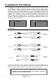
PLUGGING UP THE CABLES The GL2200 uses professional grade 3-pin XLR, 1/4" TRS jack and RCA PHONO sockets. Where possible use balanced connections to prevent noise and interference pickup especially on long cable runs. Avoid running audio cables next to AC mains, computer or lighting cables, near thyristor dimmer units or power supplies etc. The use of low impedance sources such as good quality microphones of 200 ohms or less significantly reduces interference pickup.
CONNECTING CHANNEL INPUTS Both microphone and line sources such as keyboards, replay devices and effects processors can be plugged into either the jack or XLR input for convenience. The channel accepts a wide 70dB range of source levels. The balanced 3-wire input provides the best immunity to interference pickup on long cable runs. CONNECTING TO INSERTS You do not need to plug anything into the insert socket for normal operation.
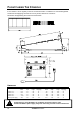
FLIGHTCASING THE CONSOLE If the console is to be regularly moved we recommend that it is installed in a foam-lined flightcase. At all times avoid applying excessive force to any knobs, switches or connectors. Dimensions for flightcasing the console are shown below: DIMENSIONS Unpacked Packed Width depth height weight(kg) Width depth height weight(kg) GL2200-412 ........................548 ............ 572 ............ 155 ............ 16.....................700 ............ 750 ............ 280 ...........
MONO INPUT CHANNEL The mono input channel is designed using a very high quality analogue signal path to ensure absolute sonic purity for microphone or line level sources. 48V 1 Ø PAD -30dB 0 GAIN 40 30 MIC INPUTS Plug a microphone source into the XLR input. If you leave the jack input unplugged then the PAD (LINE) switch becomes a 30dB pad for the microphone. This lets you use the XLR input for high output microphones, or for line level sources.
48V 1 Ø PAD -30dB 0 GAIN The 2 mid frequency bands MF1 and MF2 can be swept across a wide frequency range to tune into the exact frequency required; useful for getting the best out of microphones or for tuning out troublesome feedback. The mid bands are overlapping with a Q of 1.6 and can boost or cut in excess of +/- 15dB. The centre flat position is detented for quick resetting.
STEREO INPUT CHANNEL Two stereo input channels are included as standard. Each features a 4-band EQ, 6 aux sends and group routing. Use this channel for stereo sources such as keyboards and two track players, or for returning additional effects processors to the mix and monitors. A mic input is included so that you can use the channel for additional mics when needed. The stereo line input can still be routed to the mix while using the channel mic input. The stereo inputs are on separate TRS jacks.
48V 12 Ø 30 20 40 50 MIC GAIN 60dB 10 MIC TO TALK 10 0 LINE GAIN OO 20 LINE TO L-R MIC LINE 0 HF 12kHz -15 +15 0 MF1 2.5kHz -15 +15 0 MF2 250Hz -15 +15 0 LF 60Hz -15 +15 EQ IN AUX 1 MIC TO TALK ENABLE BAL positions the channel signal within the stereo image or between L-R and the groups when the routing switches are selected. The centre position is detented for quick resetting. MUTE switches the signal off when pressed regardless of fader position.
STEREO RETURNS HF 12kHz -15 +15 0 LF 60Hz -15 +15 AUX 1 0 OO +6 OO +6 AUX 2 0 BAL L R ODD EVEN MUTE PFL 10 L-R 1-2 5 0 5 10 20 Two stereo return inputs are provided with 2-band EQ, sends to auxes 1 & 2 and routing to L-R mix or groups 1-2/3-4. These are normally used to return the effects (‘wet’) signal, usually from a stereo device, to the mix. They can also be used for additional line inputs to the mix.
GROUP OUTPUTS GROUPS GRP/AUX 1-2 REVERSE PEAK PEAK +6 +6 0 0 SIG SIG 1 2 L-R C PAN L-R C PAN L R L MUTE R MUTE AFL AFL 1 2 10 10 5 5 0 0 5 5 10 10 20 20 Group outputs are controlled by 100mm travel faders which offer a further 10dB boost above the normal ‘0’ dB operating level. MUTE switches the group signal off when pressed regardless of fader position. Muted channels are indicated by red LEDs.
MODE SWITCHING The GL2200 features a set of GROUP/AUX REVERSE (REV) switches, which can transpose the AUX and GROUP controls in pairs. These switches are recessed to avoid accidental operation. Set using a pointed object or a pen tip. This feature allows you to set the operation of the console for Front Of House, Stage monitor or a combination of both (Dual mode). With the switches out, the groups operate in the conventional manner, channel grouping using the channel routing switches.
MASTER & MONITOR LAMP Plug in a standard 12V “gooseneck” lamp to provide illumination of the control panel. This should be a BNC connector type with a current consumption of no more than 350mA.
OSCILLATOR/PINK NOISE & TALKBACK The GL2200 oscillator section provides for two modes of operation: 1kHz Tone Mode A 1kHz sinewave is provided for setting up input levels on external devices, such as recording equipment, FX processors and so on. Pink Noise Mode A ‘pink noise’ signal, can be used to check the phase and overall frequency response of a loudspeaker or an array of loudspeakers or for analysing the acoustics of an auditorium. Pink noise produces equal sound energy per octave over the audio band.
FRONT OF HOUSE MONO 2 1 MONO 4 This example shows the 4 groups, L - R and Mono outputs feeding a 7-stack FOH amplification system. The groups provide independent control of the additional left and right loudspeaker stacks or may be used for zone feeds or for subgrouping to the L-R mix. 3 GROUPS 1 & 2 L R GROUPS 3 & 4 INSERTS LR 5 The inserts on the channels and outputs may be used for outboard effects and signal processing devices such as compressors, limiters and graphic equalisers.
STAGE MONITOR STAGE MONITORS 6 1 5 2 4 3 mic splitter AMPLIFIERS GRAPHIC EQUALISERS R inserts GRAPHIC EQUALISERS Graphic equalisers plugged into the console inserts are an invaluable aid to reducing on-stage acoustic feedback and enhancing the clarity of the monitors. Using AFL allows the stage engineer to check the operation of the equalisers in the listen wedge monitor. It is best to use the same type of loudspeaker for the engineer's monitor as those used on stage.
DUAL MODE R L MULTITRACK RECORDING Connect the inputs of the multitrack to the aux jack outputs. These are now the group mix outputs. Any unused multitrack inputs can be connected to the channel direct out sockets to record each channel on a separate track for mix down later.
FRONT PANEL LAYOUT 48V 10 48V 11 Ø 48V 12 Ø 30 GAIN 50 MIC GAIN 40 30 40 60dB 10 - 10 20 60 30 10 -15 OO LINE GAIN 20 OO -15 +15 0 SEND OO RECORD AUX 1 +10 OO OO +15 L-R OO +6 L 0 +6 BAL 3kHz +6 AUX 2 0 LINE TO L-R OO RETURN +10 REPLAY TO 0 +6 AUX 2 20 LINE TO L-R -15 +15 OO LINE GAIN 0 HF 0 0 100Hz 12kHz 0 60Hz AUX 1 10 0 2-TRACK 0 60Hz MIC TO TALK LAMP +15 LF 60dB 10 50 PAD -15 LF 50 MIC GAIN POWER +15 0 20 40 -30dB 0
REAR PANEL LAYOUT 2-TRACK RETURN MONITOR TIP L RING R AUX 6 20 R AUX STEREO RETURN 19 AUX 5 L/MONO 18 R AUX 4 STEREO RETURN AUX 3 2 17 L/MONO SYS-LINK IN L/MONO AUX 1 13 STEREO IN STEREO IN 16 14 R GRP MIC INSERT R L INSERT INSERT INSERT M INSERT 3 OUT INSERT INSERT INSERT INSERT 10 9 8 7 6 LINE IN LINE IN LINE IN LINE IN LINE IN INSERT INSERT INSERT INSERT INSERT 5 4 3 2 1 LINE IN LINE IN LINE IN LINE IN LINE IN R 12 MIC 11 MIC/LINE
INTERNAL LINK OPTIONS The console is set to satisfy most applications that should be encountered. However, the following internal link options are offered to provide alternative settings for those applications that may require them. These options involve resoldering of circuit board links and should only be carried out by competent technical personnel. Further information is available in the GL2200 SERVICE MANUAL and from your agent. MONO & STEREO INPUT 1.
GL2200 CUE SHEET - INPUTS Copy this sheet and use it to record the console settings.
GL2200 CUE SHEET – MASTER & INPUTS Copy this sheet and use it to record the console settings.
AUX 1-6 GRP 1-4 LEFT RIGHT P/AFL SL BLOCK DIAGRAM L-R =SYSLINK OPTION AUX1-2 4-BAND 2-SWEEP EQUALISER LINE IN MONO CHANNEL x10, 14, 22 or 30 PEAK +6dB 0dB SIG HF TALKBACK SIGNAL FROM STEREO INPUT EQ IN PAN MUTE + 2= + L-R 3-4 MF2 L-R LF RING = RETURN 0dBu - LO-CUT FILTER PRE FADER TIP = + STEREO RETURN L/MONO HF MUTE - LF R AUX 1 + POST-EQ POST-MUTE PRE-EQ PRE-MUTE SUM AUX 2 AFL PRE-FADE POST FADER RING = - 0dBu BAL 1-2 (3-4) TIP = SEND 2-BAND EQUALISER FADER 1