ALLEN&HEATH WARNING – HIGH VOLTAGES Power Supply Unit (PSU) work should only be carried out by qualified personnel. We recommend that you use an approved Allen & Heath service centre for all power supply work. Please contact your local Allen & Heath distributor for more details. http://www.allen-heath.
*/ 5533 Audio mixing console 6(59,&(#0$18$/ PUBLICATION: AP3389
CONTENTS Introduction ............................................................................................................................3 Service and Technical Support ..............................................................................................3 Safety Warning & General Precautions .................................................................................3 The GL2200 Range & Options ...........................................................................................
Introduction The information presented in this manual is intended for competent technical personnel to carry out service and product support for the GL2200 range of consoles. We assume that the reader is familiar with the related electronic theory and audio terminology, and is able to carry out servicing, faultfinding and repair of audio equipment of this type. Service personnel should also be familiar with audio systems, mains earthing and power requirements, as well as handling precautions.
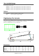
The GL2200 Range 12, 16, 24 and 32 channel models GL2200-412 GL2200-416 GL2200-424 GL2200-432 10 mono, 2 stereo, 4 groups, 6 aux, 2 stereo returns, L, R, Mono sum 14 mono, 2 stereo, 4 groups, 6 aux, 2 stereo returns, L, R, Mono sum 22 mono, 2 stereo, 4 groups, 6 aux, 2 stereo returns, L, R, Mono sum 30 mono, 2 stereo, 4 groups, 6 aux, 2 stereo returns, L, R, Mono sum Options GL2200-SL1 RPS9 Sys-link buss expander, one kit per console 2U rack mount power supply for backup Flightcasing The Console If the
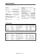
Specifications 0 dBu = 0.775 Volts rms 0 dBV = 1 Volt rms HEADROOM:............................................................ +21dB MAX OUTPUT: ..............……XLR +25dBu 2kohm max load ...........................................JACK +21dBu 2kohm max load METERS: L, R……………….peak reading 12 bar LED Groups 1-4……….peak reading 4 segment LED Channels…………peak reading 4 segment LED PEAK LEDs: ...........................
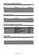
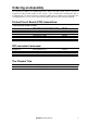
Ordering a GL2200 Console To order a new console please specify the model number and AC mains voltage required.
Ordering an Assembly The following assemblies are supplied fully tested. Please note that several of these need to be assigned according to their position in the console. This is achieved by soldering wire links or assignment pads. It is best to check the assignment settings of the assembly you are replacing before removing it from the console. Please quote the description and order code for the part required.
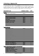
Ordering a Spares Kit It is recommended that the spares kit order code 002-481 is held and maintained by the service agent to enable in-field service repairs to the GL2200 independent of the ALLEN & HEATH factory. Commonly available items such as resistors, capacitors, tools and soldering equipment are not included. The contents of the kit are listed below and are supplied in a cabinet of drawers. Individual spare parts may be ordered. Please quote the description and order code for the part required.
Pot 10K centre click (103AC 14mm wide) Pot 5K (502RD 11mm wide) Fader 10KA x 2 60mm Fader 10KD 100mm Fader 10KD x 2 100mm Switch 2PCO Latching 90 Deg Switch 4PCO Latching Switch 2PCO Momentary Jack Socket Headphone XLR 3 Pin Female Vertical PCB Mount XLR 3 Pin Male Vertical PCB Mount Molex 0.1” Male 10 Pin 90 Deg Molex 0.
10 0 30 -15 MF2 GL2200 SERVICE MANUAL 3-4 1-2 L-R PFL 0 0 30 0 0 0 0 0 0 +6 +6 +6 +6 20 30 OO OO 0 0 10 5 0 5 10 MUTE EVEN R PRE +6 +6 0 0 0 0 EQ IN + 15 + 15 1kHz + 15 PRE 20 3-4 1-2 L-R SIG C 0 0 30 10 5 0 5 0 PFL ODD L OO OO OO OO OO OO -15 PAN AUX 6 AUX 5 AUX 4 AUX 3 AUX 2 AUX 1 60Hz -15 0 + 15 15kHz 250Hz 0 10 MF2 LF -15 35Hz MF1 +6 SIG 0 50 100Hz 60 30 40 3kHz +6 MUTE EVEN R PRE +6 +6 PRE +6 +6
INSERT 23 LINE IN MIC/LINE IN DIRECT OUT 23 INSERT 24 LINE IN MIC/LINE IN DIRECT OUT 24 DIRECT OUT 21 22 MIC/LINE IN LINE IN 21 INSERT DIRECT OUT MIC/LINE IN LINE IN 22 INSERT MIC/LINE IN DIRECT OUT MIC/LINE IN DIRECT OUT 19 DIRECT OUT 20 MIC/LINE IN 18 LINE IN INSERT 18 INSERT LINE IN LINE IN 19 20 INSERT 17 DIRECT OUT MIC/LINE IN LINE IN 17 INSERT 5 L 5 OUT 6 SEND 2-TRACK RETURN R OUT M OUT MONO AFL/PFL L INSERT 6 INSERT R AUX MONITOR AUX TI
AUX 1-6 GRP 1-4 LEFT RIGHT P/AFL SL BLOCK DIAGRAM L-R = SYSLINK OPTION LEVEL AUX1-2 4-BAND 2-SWEEP EQUALISER MONO CHANNEL x10, 14, 22 or 30 PEAK + 6dB 0dB SIG -30dBu + DIM AUX5-6 PINK NOISE GEN PRESS TO TALK TALKBACK SIGNAL FROM STEREO INPUT FADER HF ON SELECT AUX3-4 PFL PAD LINE IN OSC/PINK NOISE /TALKBACK 1KHz OSCILLATOR GRP1-4 GAIN STEREO RETURN x2 PFL BAL MF1 EQ IN MIC/LINE IN PAN MUTE + 2= + L-R 3-4 MF2 RING = RETURN - LO-CUT FILTER PRE FADER POST-EQ POST-MUT