
User guide


10 GL2800 User Guide
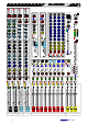
MONO
INPUTS x 8
MONO I/P x 6
ST I/P x 2
MASTER
SECTION
MONO
INPUTS x 8
MONO
INPUTS x 8
MONO
INPUTS x 8
MONO
INPUTS x 8
MONO
INPUTS x 8
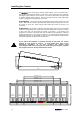
GL2800-840 = 1398
GL2800-848 = 1625
GL2800-856 = 1852
GL2800-832 = 1171
GL2800-824 = 944
650
640
6
3
4
5
168
9
19
62
58
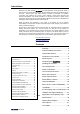
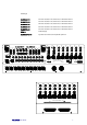
Installing the Console
The GL2800 has a space saving, compact chassis design. This is convenient both in
saving seats for the paying audience in a busy venue, and in reducing the size, complexity
and weight of flight casing for on-the-road use. The control surface has a 10 degree slope
for optimum visibility during operation. The rear connector panel has a split angle design
for ease of plugging and unplugging the connectors.
Free Standing The console has rubber feet fitted for free standing operation on a flat
surface. Make sure the surface is well supported, stable and big enough for the console to
sit securely on all its feet. Allow enough space behind the console for access to its
connectors.
Flight Casing The console is shaped for easy flight casing. Make sure it is supported
on all sides using suitably thick, shock absorbent foam intended for this purpose. Ensure
no part of the case or its lid touches the controls or connectors. If you include a rear
‘doghouse’ to house the connections make sure the cables can be supported in a way that
prevents putting stress on the console connectors. To prevent transit damage through
inadequate protection, we recommend you have the flight case supplied or approved by a
professional, specialist equipment case manufacturer.
Do not obstruct the heatsinks or ventilation openings on the power unit. Ensure
adequate air flow around its surfaces. To avoid audible hum, buzz or other
performance degradation, do not place equipment that radiates strong
electromagnetic fields such as the power unit, other mains power supplies, amplifiers
and computers next to or directly underneath the console.