ALLEN&HEATH GL4800 USER GUIDE Publication AP6150
Limited One Year Warranty This product is warranted to be free from defects in materials or workmanship for a period of one year from the date of purchase by the original owner. To ensure a high level of performance and reliability for which this equipment has been designed and manufactured, read this User Guide before operating.
Important Safety Instructions WARNINGS - Read the following before proceeding : CAUTION ATTENTION: RISQUE DE CHOC ELECTRIQUE – NE PAS OUVRIR Read instructions: Read and retain these safety and operating instructions for future reference. Adhere to all warnings printed here and on the console. Follow the operating instructions printed in this User Guide. Do not remove cover: Operate the console with its underside cover correctly fitted.
General Precautions Damage To prevent damage to the controls and cosmetics avoid placing heavy objects on the control surface, scratching the surface with sharp objects, or rough handling and vibration. Environment Protect from excessive dirt, dust, heat and vibration when operating and storing. Avoid tobacco ash, smoke, drinks spillage, and exposure to rain and moisture. If the console becomes wet, switch off and remove mains power immediately. Allow to dry out thoroughly before using again.
Introduction Welcome to the Allen & Heath GL4800, the latest generation of the popular GL series of multi-function audio mixing consoles. We have tried to keep this user guide brief and to the point. Please read it fully before starting. Included is information on installing, connecting and operating the console, panel drawings, system block diagram, technical specification and cue sheets.
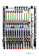
LAMP LAMP +48V -20 40 LINE MIC 50 6 -14 PAD 30 10 GAIN LEV -20 -15 -10 -30 -5 LEV -20 -15 -10 -30 -5 0dB GL4800 MIC LINE 0dB 20 -10 -30 POLARITY -10 10 -15 LEV -20 -10 -30 -5 0dB -15 LEV -20 -10 -30 -5 0dB -15 LEV -20 -10 -30 -5 0dB -15 +48V LEV 2TRK RETURN -5 0dB 0dB ON ON ON ON ON ON AFL AFL AFL AFL AFL AFL +5 MULTI FUNCTION AUDIO MIXING CONSOLE OUT REV OUT REV OUT REV OUT REV OUT REV OFF POST PRE 7kHz 3k -20 10k -15 20kHz P
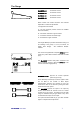
The Range GL4800-24 24 channel console GL4800-32 32 channel console GL4800-40 40 channel console GL4800-48 48 channel console Stereo models can include mic/stereo line channels dependant on customer specification.
Introducing the Allen & Heath GL4800 The GL4800 offers the professional user an uncompromised feature set and performance for the latest techniques in live sound engineering and recording. The console is available in 24, 32, 40 and 48 channel sizes with an external 3U rack power unit. A built-in VU Meterpod is fitted as standard. An optional SysLink V2 input expander system is available.
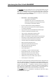
Here are just a few key points we considered when specifying the GL4800: Affordability We understand your need to work within a realistic budget and know you want to get the very best return for your investment. We know too that even the lowest budget shows put the same tough demands on the operator who wants the reassurance of continued reliability and intuitive control, the satisfaction of achieving that special sound, and the functionality to deal with the trickiest situations.
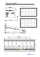
Dimensions and Weights UNPACKED Width Depth Height Wt(kg) GL4800-824 1166 (46”) 748 (29”) 285 (11”) 47(104lbs) GL4800-832 1421(56”) 748 (29”) 285 (11”) 57(126lbs) GL4800-840 1676(66”) 748 (29”) 285 (11”) 67(148lbs) GL4800-848 1931(76”) 748 (29”) 285 (11”) 77(170lbs) RPS11 483(19”) 232 (9”) 135 (3U) 10(22lbs) 232 132.
Specifications Performance 0dBu = 0.775 Vrms Reference for high level equipment +4dBu = 1.
Mode Switching Protected underpanel mode switches set the console architecture according to the required application, for example FOH or stage monitor. Select these using a pointed object. GL4800 DIR OUT routes the channel direct out signal through the aux 10 pre/post selector and level control.
AUX 1-10 GRP 1-8 LEFT RIGHT MONO MTX A-D PFL AFL System Diagram S =SYSLINK INPUT OPTION 2-TRACK RETURN LEV L IN REPLAY TO L-R - OUTPUT REVERSE (LR2 / AUX 9-10) - R LEV ON - L(R)2 OUT - STEREO PFL AFL AUX - L(R)2 0dBu IMPEDANCE BALANCED AUX OUTPUT REVERSE (MTX 1-4 / AUX 5-8) MTX MIX LEV ON MTX (1-4) OUT - TB TO AUX ENABLE 0dBu IMPEDANCE BALANCED GROUP/AUX REVERSE MTX TO AUX (1-4) S - MATRIX (1-4) AFL AUX MIX PEAK +6 0dB SIG INSERT SEND AUX (1-10) SML SML FADER MAIN + -
Connectors Professional gold plated connector types are used to ensure continued reliable operation. All the console main inputs and outputs are balanced XLRs. All 1/4" jacks are 3-pole TRS for operation with balanced or unbalanced equipment. Inserts are provided on all channel inputs, and on Groups, L, R, Mono and all Aux outputs.
Sys-Link V2 Expander Option Available as a kit to be fitted to the console to expand the busses. Uses 2 37-pin D-type connectors (input A and B). Operates at -2dBu line level. Input option available only. Refer to your Allen & Heath agent for further details. Group/Aux/L/R/M Insert Send Used to send the output signal to external effects and signal processing equipment such as graphic equalisers, delays and compressors, post-mix amp and pre-fader. SEND INSERT 3-pole 1/4" jack socket (tip = hot).
R MTX METERPOD 4 3 2 7 AUX8 L LOCAL Recessed 16-pin dual row header for connection to the meterpod. 1 6 5 R2 Local Stereo Monitor MATRIX L2 AUX10 9 OUT2 MODE FOR MATRIX/LR2 ON XLR + INSERTS = SEND OUT REV SEND INSERT RET AUX 10 AUX 9 R2 For connection to a stereo amplifier/speaker system for LR, AFL/PFL monitoring local to the console. 3-pole 1/4" jack sockets (tip = hot). Impedance matched 50ohm 0dBu nominal line level.
Earthing The connection to earth (ground) in an audio system is important for two reasons: 1. SAFETY - To protect the operator from high voltage shock associated with the AC mains supply feeding the system, and 2. AUDIO PERFORMANCE QUALITY - To minimise the effect of earth (ground) loops which result in audible hum and buzz, and to shield the audio signals from external interference.
Connecting Power Connect only the Allen & Heath power unit specified for the console. The standard unit for GL4800 is the RPS11. This is an external 3U 19" rack mounted unit that connects to the console via the separate DC cable supplied. The RPS11 is a low noise linear design that converts AC mains voltage to the DC voltages required to power the console. It also provides +48V phantom power for use with high quality powered microphones.
Matching the Signal Levels For best performance it is important that the connected source signals are matched to the "normal operating level" of the console. Similarly the console outputs should be correctly matched to the operating levels of the connected amplifiers and destination equipment. If too high the signal peaks will be clipped resulting in a harsh distorted sound, and if too low the signal-to-noise ratio is reduced resulting in excessive background hiss and noise.
The MONO Input Channel +48V - Feeds +48V to pins 2 and 3 of the input XLR for condenser microphones which require phantom power.
AUX 0dB 1 +6 AUX 2 0dB +6 AUX 0dB 3 +6 AUX 0dB 4 +6 POST PRE AUX 0dB 5 +6 AUX 6 0dB AUXILIARY SENDS - Route the channel signal to one or more of 10 auxiliary send busses. These are independent from the main outputs and may be used for effects sends and monitor mixes. The sends are grouped 1-4, 5-8, and 9-10. Each group may be selected pre or post channel fader. A further 6dB of boost above 0dB normal channel level is available on the send control.
The STEREO Input Channel +48V POLARITY MIC LINE 0dB 20 PAD 30 10 -10 10 XLR GAIN 40 50 LINE MIC 6 -14 60 40dB 50Hz 30 HPF 100 200 20 OFF 400Hz POLARITY (R) STEREO WIDTH MONO REVERSE -5 WIDE 0dB STEREO GAIN -10 +5 -20 -30 +10dB The stereo channel has two independent input sections: XLR IN for mono microphone or line input, and STEREO LINE IN on jacks for sources such as stereo keyboards, voice modules and effects returns.
M-S Stereo Microphones L Stereo Microhones R MIDDLE This example shows two cardiod microphones arranged as an X-Y coincident pair. This minimises the phase differences which can cause problems when the mics are arranged as a spaced pair.
GROUP -20 -15 -10 -30 LEV -5 0dB ON AFL OUT REV POST PRE -20 -15 OUTPUT TRIM -10 -30 -5 0dB GRP 8 ENABLE 8 +16 MATRIX MASTER - Controls the output of the matrix mix. Adjust LEV to trim the output level to match the connected equipment. ON switches the output on or off, ideal for checking the effect of individual or combinations of speakers in a multispeaker system. AFL lets you monitor the signal post level trim, post insert, but pre ON switch.
THE CONSOLE MATRIX - The GL4800 includes a versatile 11 x 4 output matrix. This comprises four independent outputs each with level control, ON switch and AFL monitoring. Each matrix mix is created from the desired combination of group (x8), L (left), R (right) and M (mono) signals. The level of each source is adjusted using the matrix SEND controls above the main faders in much the same way as the channel aux sends are used. The output is selectable to a TRS jack or XLR with insert.
LR -15 -20 -10 -30 LEV -5 0dB ON AFL THE CONSOLE LR AND LR2 OUTPUTS - In addition to the main L and R outputs the GL4800 includes a secondary pair of outputs called L2 and R2. These follow the LR mix and may be selected either pre or post LR faders. As with the matrix outputs an OUTPUT REVERSE switch is included on each to swap the L(R)2 jack output with aux 9(10) XLR and to switch in the insert.
MONO 2TRK RETURN -5 LEV -2 0dB -10 +5 -20 +8 +10dB -30 REPLAY TO L-R PFL AFL ACTIVE PFL STEREO PFL MONO M +16 +9 +6 +3 0 -3 -6 -9 -12 -15 -20 -30 48V +V -V 2-TRACK STEREO RETURN - The incoming level can be trimmed from OFF to +10dB gain and routed direct to the LR mix for intermission or recording replay. Monitor the signal post LEV trim and pre REPLAY switch using STEREO PFL which automatically overrides the signal in the headphones and local monitor.
MTX 0dB 1 +6 MTX 0dB 2 +6 MTX 0dB 3 +6 MTX 0dB +6 POST PRE WEDGE MODE M MIX AFL/PFL 4 M THE MONO MIX - The GL4800 includes an independent mix buss for the M (mono) output. Each channel and group can be routed direct to this buss by pressing the related M routing switch. The signal is sourced pre PAN control so that the mono mix is not affected when the stereo mix image is adjusted. The M output can be a different mix to LR.
LAMP CONNECTORS - Two top panel 4-pin XLR connectors are provided for connection to gooseneck lamps. It is recommended that these are the standard 12V 2.5 watt type. LAMP THE CONSOLE MONITOR - The GL4800 offers a comprehensive signal monitoring system. Apart from the extensive metering facilities there is a monitor section which operates independently of the main outputs.
The Mute System SNAPSHOT Each GL4800 input channel, group, aux send and main output (L,R,M) is provided with a mute switch. This turns the audio signal on or off. The GL4800 provides a 'soft' mute system controlled by a built-in microprocessor which gives far greater control and versatility than the conventional systems found in other consoles. A ramped FET audio element on each channel provides silent muting under control of the microprocessor.
The Mute Switch Press MUTE once to mute the channel signal. The red LED will turn on. The audio signal will turn off (channel muted). Mute affects the post-fade signal and will also affect the pre-fade signal if the internal option links are configured to do so (factory default setting). Press MUTE again to turn the mute off. Turn All Console Mutes Off or On SNAPSHOT MIDI CHANNEL MODE ACTIVE PATCH SOLO IN-PLACE It is often useful to turn off (clear) all the console mutes or to turn them on (set).
Mute Groups A mute group lets you mute a selected combination of channels with a single key press. Applications include muting unused channels when mixing different bands, muting all channels except 2-track playback during intermission, muting all effects, muting a bank of radio mics during an instrumental number, muting stage mics during scene changes, and so on... The GL4800 includes 8 mute groups controlled by a bank of large buttons to the right of the master faders.
Program a Mute Group Press EDIT GROUP The red LED will start flashing. This puts the mute system into 'edit mode'. The mute groups are programmed or edited 'off-line'. This lets you change groups during a live show without affecting the mute status of the channels. Press the MUTE GROUP to be programmed. The mute group LED will start flashing. The green SAFE/PREVIEW LEDs below the MUTE switches will indicate which channels are part of the group. EDIT GROUP Press the channel MUTE switches.
Turn All Mutes Off or On in a Group SNAPSHOT MODE ACTIVE PATCH SOLO IN-PLACE SHIFT EDIT SAFES Turn Off or On all Mutes in a Group STORE Press EDIT GROUP PREVIEW < > MIDI CHANNEL It is often useful to turn off (clear) or turn on (set) all the console mutes within a mute group. This is done in 'edit mode' so that the console mutes are not affected while the group is being edited. AUTO INCREMENT RECALL DISABLE The red LED will start flashing. This puts the mute system into 'edit mode'.
Mute Safes Mute groups, snapshots and MIDI overwrite the console mutes with the settings held in memory or an external controller. You may want to prevent selected channels being overwritten, for example if you need to repatch mic channels to deal with a cable break during a live show. In this situation it would not be convenient to reprogram the mute groups and snapshots. Instead you would operate these channel mutes manually until the show ends.
Mute Snapshots A mute snapshot lets you store the console mute on/off settings to be recalled with a single key press. This is much like taking a 'snapshot' of the console settings. Mute snapshots are used extensively for scene or song changes during live performance. The advantage is quick access to complex changes, a growing requirement with the more sophisticated sound control specified today.
The Snapshot Display Normal Mode Shows selected snapshot number Indicates which snapshot which will overwrite the console mutes when you press RECALL, or be overwritten when you press STORE. The ACTIVE dot tells you how the displayed number relates to the current console mute settings: SNAPSHOT MIDI CHANNEL MODE 0 to 127 or ALL ACTIVE on : ACTIVE PATCH Displayed snapshot is the last snapshot recalled. Console mutes are the same as the displayed snapshot (except for channels made 'safe').
Scroll Through the Snapshot Numbers The 128 snapshots are numbered 0 to 127 . Before 0 there is a special snapshot called ALL . This is described later. Press ∧ or ∨ to increment or decrement to the required snapshot number. Hold down ∧ or ∨ for fast scrolling to the required number. The ACTIVE dot will indicate the status of the current console mutes against the selected snapshot number. See the section on SNAPSHOT DISPLAY.
The ALL Snapshot Between snapshot 127 and 0 is a special snapshot function called ALL This lets you overwrite all 128 snapshots with the current console mute settings. You would normally do this before programming the snapshots for a particular show. Typical use would be : Turn all mutes off in all snapshots (clear), then edit the mutes on for required channels. Turn all mutes on in all snapshots (set), then edit the mutes off for required channels.
Solo-In-Place Solo-In-Place is a system for checking individual signals or combinations of signals in the mix. This is done by muting all channels except for the channel/s being soloed. The position and relative levels of the signal to all the outputs is retained. Solo-In-Place affects the main outputs. This should not be confused with the PFL/AFL monitoring system which affects only the monitor outputs.
Solo Safes Solo-In-Place can mute all the console mutes including channels, aux sends, groups and main outputs. To hear the effect of soloed channels the required outputs should not be muted. You may also wish to always hear the effect of signal processing devices such as reverbs connected to the console aux sends and returns. Here, the aux sends and channels allocated as effects returns should not mute when solo is activated.
MIDI The Musical Instrument Digital Interface (MIDI) was originally conceived to standardise the interconnection between keyboards and other instruments. It is now found on all manner of equipment including sound and lighting consoles, effects devices and computers. Sophisticated recording and live sound control is now possible by interfacing sound consoles with other MIDI equipment. The GL4800 includes a full opto-isolated Musical Instrument Digital Interface (MIDI) system.
SNAPSHOT Select the Console MIDI Channel Press and hold SHIFT + PREVIEW SNAPSHOT together to enter 'MIDI mode'. MIDI CHANNEL The display MIDI dot turns on and the current MIDI channel number is shown. While holding SHIFT + PREVIEW channel numbers using ∧ or ∨ scroll through the MIDI Leave the display set to the required MIDI channel number . 1 to .16 SHIFT Release SHIFT + PREVIEW to exit. Disable the Console MIDI System Enter 'MIDI mode' as above.
Channel Mutes Pressing any console mute switch transmits a MIDI Note On message unless MIDI has been disabled. Similarly receiving the correct Note On message will control the channel mute unless it has been made 'mute safe' or MIDI disabled. Console mutes are mapped to MIDI Note numbers as shown. Running status is supported on receive and transmit.
MIDI Dump Data When a MIDI DUMP OUT is performed the entire contents of the console memory is transmitted down the selected MIDI channel. This includes the current console mute settings, mute groups, snapshots, safe settings, solo settings, console modes, and console MIDI channel number. When a MIDI DUMP IN is received the console memory is completely overwritten. SNAPSHOT This is ideal when you want to archive settings and recall them at a later date, for example a re-run of a previous performance.
Technical Support Should you have any queries about the GL4800 console automation system please quote the console model, serial number and software version number in any communication with Allen & Heath or appointed service agent. The system has been designed and tested to be reliable under the harsh conditions typical of live sound 'on the road'.
Hard Reset Should the console memory become corrupted it can be reset to the factory defaults by performing a hard reset : EDIT GROUP Hold down EDIT GROUP + PREVIEW GROUP while powering up the console. The following condition set : PREVIEW All console mutes turned on. Snapshot display shows 0 All mute snapshots cleared (mutes turned off). All mute groups cleared (mutes turned off). MIDI channel set to 16. No mute safes set. No solo safes set.
Front-of-House with recording STAGE MONITOR WEDGE SPEAKERS 1 2 4 3 L M R POWER AMPLIFIERS EFFECTS L R 5 2TRK REPLAY 6 to broadcast M 7 1 8 2 3 inserts 4 L2 DELAY R2 DELAY L2 MULTITRACK RECORDING R2 GL4800 (MAIN) LISTEN WEDGE (BACKUP) MONITOR 10 MIC IN L B DC POWER IN 2-TRACK RETURN MONITOR 4 MONITOR 3 SEND SEND MONITOR 2 MONITOR 1 STAGE MONITOR MODE SEND AUX RET INSERT LINE IN INSERT SEND SEND RET OUT REV INSERT MODE AUX10 THRU R STEREO GRAPHIC EQ
Using the GL4800 for Front-of-House (FOH) The console is positioned within the listening area so that the sound fed to the audience can be accurately balanced and controlled. In larger systems the performers monitors may be controlled from a separate console positioned at the side of the stage (on-stage monitor). Where this is not possible the monitors are controlled from the FOH console.
The Monitors Otherwise known as foldback or cue sends, the monitor mixes are created from the console aux sends. These feed amplifier/speaker systems positioned on-stage for the performers, backstage for the stage crew, in the pit for the orchestra, and so on. The channel aux sends are usually set PRE (pre-fade) for monitors so that they are independent of the front-of-house mix levels.
Live 2-Track Recording A simultaneous stereo recording can be made of the performance by feeding additional console outputs to a 2-track such as a cassette or DAT recorder. The GL4800 offers several methods depending on the application. In each case a separate output level trim is provided so that you can match the console to the operating level of the recorder, usually +4dBu (high level) or -10dBV (low level). AFL is provided so that the recording level can be checked independent of the live mix : 1.
On-Stage Monitor 6 SIDEFILL 7 L 10 9 8 SIDEFILL R STAGE MONITOR WEDGE SPEAKERS 1 2 5 4 3 POWER AMP x12 Mixing system for on-stage control of performers monitor loudspeakers (wedges). Provides 12 monitors (10 wedges + LR sidefills) and a dedicated engineers 'listen' wedge output.
Using the GL4800 as a Monitor Console The GL4800 can be easily configured to function as a dedicated 12 buss on-stage monitor console (10 wedges plus side fills), 14 buss (10 wedges plus 4 IEM), or many other combinations. In this example, the console is positioned at the side of the stage giving the monitor engineer a clear view of the performers on stage.
Stereo In-Ear Monitoring The LR mix and/or the matrix can be used to feed a stereo in-ear monitoring system, often preferred by lead performers. Using LR, a more precisely balanced mix can be created using the channel faders and pan controls. It is usual to plug limiters into the LR inserts to avoid possible hearing damage to the performer. Check the in-ear mix using the stereo headphones or by feeding the local monitor output to a duplicate in-ear system.
Multi-Speaker System 6 Speaker system driven from the matrix and LR2 outputs. Provides output balance and level trim independent of the mix levels. All outputs are balanced XLR with inserts for EQ, delay or other signal processors.
Internal Link Options The GL4800 is configured to satisfy most applications that should be encountered. However, the following internal link options are offered for those applications that may require alternative settings. These options require access to the internal circuit assemblies and resoldering of circuit board links. This work should be carried out by technically competent personnel. Further information is available in the separately available service manual and from your Allen & Heath agent.
Cue Sheet 1 of 5 Master GL4800 Copy and use this page to record your console settings.
Cue Sheet 2 of 5 8M GL4800 Copy and use this page to record your console settings.
Cue Sheet 3 of 5 4SM GL4800 Copy and use this page to record your console settings.
Cue Sheet 4 of 5 4MS GL4800 Copy and use this page to record your console settings.
Cue Sheet 5 of 5 8S GL4800 Copy and use this page to record your console settings.