DIGITAL MIXING SYSTEM Screen Reference Guide For GLD firmware Version V1.
1. Contents 7.2 Scene Crossfade ................................................... 34 7.3 Embedded Scene Recall ....................................... 34 1. Contents........................................................................2 7.4 Scene Recall Filter page ........................................ 35 1. Power Up Screens ........................................................3 7.5 Cue List Editor page .............................................. 36 2. Home Screen ................
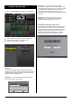
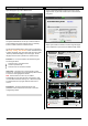
1. Power Up Screens User Scene – If a User Scene is set it is recalled automatically on login when the user is changed. It does not recall when the same user logs in, or when the system is powered up again while the same user is current. The Home screen will appear on power up If no password is set. A User Scene can be set by Admin to ensure a predetermined layout and starting point loads when a different user logs in.
To safely Power Down the GLD system - Touch the Power Down button, confirm, and then switch power off. Failure to power down correctly may result in parameter changes made up to 30 seconds before power is removed becoming lost. 2. Home Screen 2.1 Home page Lock Surface - Touch the Lock Surface button and Yes in the confirmation popup to lock the surface controls. Parameters will not be changed if the surface controls are moved while locked, for example when left unattended.
2.2 Users Login page 2.3 Open this page to log in as a different User. Quick Start page Opens a Quick Start sheet to help the new user or guest engineer learn in just a few minutes how to mix their show using GLD. The system Administrator can set up to 9 User Profiles to protect settings and reduce operator error by restricting access to certain functions for different users. Swipe up and down the screen to scroll through the page. Touch Help Menu to open the list of additional Help topics.
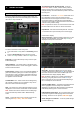
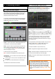
3. Processing Screen 3.2 3.1 Input Channel processing pages are accessed by pressing an Input strip Sel key while the Processing screen is selected. The Input Overview page provides a thumbnail view of all processing for the selected input channel. Name and Colour keypad Overview page – Input Channel Input channels, FX sends and returns, Mix masters and DCA masters can each be given a Name and Colour using the on-screen touch keypad.
3.3 Overview page – Mix Channel 3.4 Overview page – FX Send or Return Mix processing pages are accessed by pressing a mix master strip Sel key while the Processing screen is selected. The Mix Overview page provides a thumbnail view of all processing for the selected mix channel. FX processing pages are accessed by pressing an FX Send or Return strip Sel key while the Processing screen is selected. The page provides a thumbnail view of all processing and parameters for the selected FX.
3.5 Channel Libraries 3.6 Libraries let you store and recall presets for individual processing blocks such as EQ and Compressor, and also for the whole Input or Mix channel. Preamp page The Preamp page provides access to the Input Channel source patching, socket Preamp settings, and channel Trim and HPF. Input and Mix channel processing Libraries do not store routing, levels or assignments. The Library window lists available presets.
Note Making a channel Safe using the surface Safe key automatically makes the associated Preamp safe. Turning off Safe using the surface key unsafes the Preamp. Trim on Surface – The surface Preamp rotary adjusts Channel Trim. Consider using this in situations where you are sharing the same Preamp between channels or FOH and Monitor consoles. Trim can provide +/-24dB ‘gain’ control when the source does not have a preamp, for example input from GLD surface RCA line inputs, the I/O Port or USB playback.
3.9 Noise Gate page 3.10 Insert page The Noise Gate automatically attenuates the signal when it drops below its threshold level. For example to: You can insert external equipment or one of the 8 internal FX units into a channel or mix signal path: Reduce excessive ring on a kick or tom drum Reduce hiss on a noisy keyboard when not played.
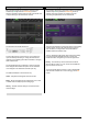
3.12 GEQ page A 28-band 1/3 octave Graphic Equaliser is provided on each of the 20 mix outputs. It can be adjusted using the touch screen or the surface faders. In - Switch the PEQ in or out of circuit. The curve turns yellow when switched in and grey when switched out. Type - The LF and HF EQ bands may be set as shelving, bell shaped or low/high cut filter response. When set as a filter the response is 12dB/octave.
GEQ Type – Use the drop-down menu to select one of four GEQ types available. These offer different types of cut/boost response: Using the faders to control the GEQ You can quickly access the GEQ on the faders for the mix with its Sel key active by: Touching the screen GEQ Fader Flip button, or Pressing the GEQ Fader Flip key to the right of the faders while in any of the mix Processing pages.
Side Chain Filter - Restricts the frequency range of the signal that triggers the compression. Use this to filter out low or high frequencies outside the range of the wanted signal thus preventing false triggering. Extreme settings can be used for special effect or frequency sensitive compression, for example 'de-essing' to compress just a range of high frequencies to reduce sibilance of a vocal. The default is the filter switched out. 3.
Delay Bypass - Touch the button to toggle the delay in or out. Use this to compare the direct and delayed signal, for example when you are time aligning delay fill speakers. 3.15 Routing Page – Input Channel view The Input Routing page lets you view and adjust the channel sends, routing, assignments and Direct Out. Input Delay Input delay can be used to time align instruments to each other or create extra ‘depth’ on stage.
DIR OUT SRC pull-up window Touch a box to toggle single parameters such as DCA and Group assignments. Touch a box to open the send panel on the right of the screen to adjust multiple parameters such as Aux send levels, assignments and Pre/Post fader settings. The screen Rotary becomes the Aux send level control. Using the GLD fader strips - Press a master strip Mix key. Current settings are shown in the channel strip LCD displays.
3.17 Routing page – DCA Master The DCA master affects the level and mute of an assigned channel back at its fader point. It is another level stage in line with the channel fader. It does not physically move the channel fader. A separate indicator next to the channel Mute key shows if it is muted by one or more DCA groups. GLD provides 16 DCA Groups. These can be used as DCA Groups (level control) or Mute Groups (mute masters).
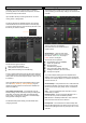
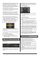
4. Meters Screen 4.2 FX and Mix Meters pages These pages show meters for all FX and Mixes available. 4.1 Input Meters page Meters for all 48 Input Channels are displayed on this page. Channel Name and Colour is shown below each meter. The Compressor Gain Reduction meter is shown to the right with the Gate Active indicator below it. These show activity in red when switched In, and in grey when switched out of circuit.
4.3 Custom 1-4 Meters pages 4.4 You can assign 4 Custom meter views. RTA The RTA provides a 1/3 octave 'Real Time Analyser' frequency display for the signal currently PAFL signal. These can be viewed in the Home or Meters screens. The RTA can be viewed in the Home or Meters screens. It also displays on the strip meters when GEQ Fader Flip is active. It separates the signal being listened to on the PAFL monitor into 31 frequency bands and shows the relative strength of each as a real time display.
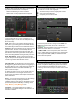
5. FX Screen PEQ – Each FX Return has a 4-band Parametric Equaliser. Touch the PEQ button to open the FX PEQ popup. Touch again to close it. Touch the Param button to choose to adjust the EQ by dragging a curve or changing values using the Rotary. 5.1 The PEQ can also be accessed by pressing Sel on the FX return (IP FX) fader strip. Front Panel view Access the FX using the FX screen or by pressing Sel keys for individual FX Send or Return fader strips. 5.
Chaining FX - FX devices can be routed to each other. For example you could patch the output of a Delay unit into a Reverb, and then return the reverb to the main mix. 5.4 FX Devices available SMR Reverb View Outputs – Touch the View Outputs button to open a window showing where the outputs of the FX device are routed. Each slot can handle up to 8 outputs depending on the device loaded. Most provide 2 outputs (stereo).
In addition there are 5 pages of scrollable ‘Expert’ pages for the Reverb which allow precision control: 2-Tap Delay Page 1 - Reflections - Source Diffusion, Size, Shape, Ref Detail. Dedicated to reflection control. Keep source diffusion and detail low to help intelligibility. Small sizes are not typical for live applications. ‘Shape’ is only available in the Plate model. Page 2 - Echoes - Echo1, Echo1 level, Echo2, Echo2 level. Separate left and right tap delay outputs from a mono’d input.
Gated Verb ADT Doubler An accurate emulation of the classic 80’s Gated Reverb plus two other variants called ‘Panned’ and ‘Powerbox’. The user interface gives instant access to Lo-cut Hi-cut decay spectrum filters and the gate envelope controls - predelay, attack, hold and release. An Automatic Double Tracking module capable of creating short echo/chorusing, classic double tracking and ‘slapback’ tape delay loops.
Speed - Determines the speed of movement across the stereo field. Chorus Preset Name is displayed. Touch and scroll using the screen Rotary for live update. This is a way of live auditioning all library presets for this module (factory, user and USB). You can also select and recall a particular preset using the Library window. Chorus derives from the late 80’s where different stereo field creation techniques influenced the sound of each chorusing unit.
Flanger Preset Name is displayed. Touch and scroll using the screen Rotary for live update. This is a way of live auditioning all library presets for this module (factory, user and USB). You can also select and recall a particular preset using the Library window. MOO 12 Stage Phaser Three classic flanger effect emulations – ‘Ambient’, ‘Vintage’ and ‘Wild’. During research of classic pedal flangers we found numerous LFO modulators and stereo splitting techniques. We implemented them all.
and relies on manual sweeping of the phase chain using the ‘offset’ control. content. Typically a low setting is common to prevent the generated sub bass upper harmonics clashing with the original bass content. Beyond mid position is only useful for Lost Fundamental mode. Offset - Shifts the operating frequency range of the Phaser. Maximum settings force the Phaser to operate in higher frequencies. Lower Offset settings allow lower frequency phase sweeps (more intense).
De-Esser Rotator Based on the flagship iLive FX engine, the De-Esser emulates the classic Auto-Threshold circuit commonly found on high end hardware units. This produces a constant sibilance reduction regardless of signal level, resulting in a more natural De-Essing process. In comparison, threshold based De-Essing produces inconsistent reduction activity which can result in unnatural vocals.
VS1 Vocal Shift Pitch Doubler VocalShift VS1 is a stereo vocal pitch shifter squeezing two channels of high quality pitch shifting into a single effect. It has a very low latency (<6ms), covers the whole vocal frequency range, and minimises the phasing and flutter artefacts common with many pitch shifters. PitchDoubler is a stereo, pitch shifting doubler effect generating the effect of additional voices from its input.
Listen - Touch to momentarily listen to the sidechain filter signal using the PAFL bus. Dynamic EQ SC Config - Left and Right signals are summed to produce a mono sidechain for each band. Choose one of two modes: Cascade - The sidechain for each band is fed from the previous band. Each band is affected by the previous band activity. Parallel - All sidechains are fed from the input to the DynEQ. Avoids band interaction. DynEQ4 is a model of the industry standard stereo 4-band Dynamic Equaliser.
Attack/Release modes - There are two manual and 4 automatic dynamics modes: Transient Controller • Peak Manual • RMS Manual • Auto Punch • Auto Opto • Slow AutoF • Fast AutoF This is an accurate model of the industry standard Transient Signal Processor. Knee - Hard or Soft (easy knee model). Transient Signal Processors provide cut and boost of the attack and sustain envelopes of the input signal. This gives the sound engineer greater control over the transient behaviour of audio programme.
6. I/O Screen 6.1 Patching Inputs - Touch an input socket to highlight it. Use the lower part of the screen to select the channel to assign the socket to. Choose the channel number using the Start box and screen rotary. dSNAKE I/O page To assign a range of input sockets touch the End box and turn the screen rotary. The sockets about to be assigned are highlighted on the screen. Use this screen to patch Input and Output sockets on the main AudioRack connected to the GLD via its dSNAKE port.
GLD rear panel sockets – XLR and RCA phono analogue I/O, and SPDIF and AES digital outputs. SOURCES pull-up window An I/O Port input could be assigned to multiple destinations, for example to one or more channels and also to the port output. Use the pull-up to see a list of all destinations for a highlighted port input. GLD top panel USB – Patching for stereo audio playback and recording. AR84 AudioRack connected to the GLD surface EXPANDER Port – 8 Mic/Line inputs and 4 Line outputs.
6.6 Monitor Outputs page 6.7 Patch GLD signals to the dSNAKE Monitor sends using this screen. MMO card in the I/O Port Up to 64 GLD inputs and 64 outputs can be assigned to an audio option card fitted to the GLD-80 rear panel I/O Port.
Note Deleting a Scene clears its contents, resets its Recall Filter to allow all parameters, and clears its name to be blank. 7. Scenes Screen 7.1 Copy - Touch to select the Scene you wish to copy. Touch the Copy button. Touch the Scene you wish to copy to. Touch the Paste button to paste the contents and filter settings to that Scene. Scene Manager page Use this screen to work with the GLD Scene memories. Note Copying a Scene copies its contents and Recall Filter settings.
7.2 Scene Crossfade 7.3 A crossfade time can be set for each Scene. This is the time it will take to fade the current levels to those in the Scene when it gets recalled. Embedded Scene Recall You can choose to automatically recall one or more other Scenes from the same or a different unit when you recall a Scene. A delay time can be set for each Scene embedded within the host Scene. Touch the Embedded Recall button to open the popup.
7.4 Scene Recall Filter parameters Scene Recall Filter page For Inputs, FX Returns, FX mix, Grp, Aux, Main Mtx: A Recall Filter can be set for each Scene to prevent certain channels or parameters being overwritten by the Scene when it is recalled. This lets you decide which parameters to recall per Scene. A Recall Filter affects just the Scene it is associated with.
7.5 Cue List Editor page A Cue List is a custom list of Scenes selected from the All Scenes list. You can drag and drop Scenes to create the Cue List. Scenes can be placed in any order and repeated any number of times in the list, or deleted from the list. Cue Lists can be named, saved, recalled and deleted. You can choose to show either the All Scenes or the Cue List window in the Scene Manager page. The current and saved Cue Lists are stored in Show memories.
7.6 Scene Safes parameters Scene Safes page For Inputs, FX Returns, FX mix, Grp, Aux, Main Mtx: Scene Safe is similar to the Recall Filter but is global affecting recall from all Scenes.
Ganging parameters 8. Ganging Screen You can gang any combination of these parameters: Input channels: Use this screen to assign up to 8 Gangs. Trim (allows ganged input level trim) HPF Gate PEQ Compressor Delay Fader Mute Pans Routing (assign, pre/post, send levels/pan) Mix masters: Trim (for Ext inputs) PEQ GEQ Compressor Delay Fader Mute Pans Routing A Gang links all or a selection of processing and routing parameters for two or more channels or mixes of the same type.
Disable PFL on Sel - Disables the interruption of the PAFL audio signal while pressing a channel processing block Sel key to open its screen view. Turn this option Off if you want to listen to (PFL) the audio signal at that point in the channel path while pressing and holding the processing block Sel key. 9. Setup Screen – Audio 9.1 PAFL Setup page These options provide great flexibility to suit different mixing applications.
SOURCE pull-up window 9.3 Use the pull-up to choose the Talkback source, set its options, adjust its gain and set its High Pass Filter. SigGen page The Signal Generator (SigGen) is a useful tool providing a steady test signal to help you align and test a live sound system. Use this page to set up the Signal Generator and route it to one or more mix outputs. Enable Latching – The default Talk switch operation is momentary (press and hold while talking).
9.4 USB Audio page Recording a stereo track to USB key: Set up and manage stereo recording and playback to a USB key. Tracks and space available are shown. Recording format – GLD records WAV files at 48kHz. Recording time – Memory required = 188KB/sec. Therefore allow: 11.5MB per minute 700MB per hour Note Maximum recording time for one track = 3 hours. To assign a recording source – Touch the Assign button to open the I/O / Surface screen to patch the source for the USB recording.
9.5 Audio Sync Setup page 9.6 I/O Port Setup page Use the Audio Sync Setup page to choose the Audio Clock Source for the GLD system. Use the I/O Port Setup page to set options associated with the audio card currently fitted to the I/O Port. Open the drop-down menu: ACE Redundant Link On – Uses Port 2 for redundant cable backup Internal - The GLD uses its internal audio clock. Use this setting when you are working with local Mic/Line audio sources connected via the GLD and its AudioRacks.
OPTIONS pull-up window 10. Setup Screen – Control 10.1 Strip Assign Setup page Any combination of inputs, FX, masters and MIDI strips can be assigned to the 4 Layers of the Fader Banks. You can 'design' your own mixing layout to suit the way you want to work. Use the pull-up to choose to sync the Layer shown on the screen with the currently selected surface Layer. Select the Bank to work with. The screen will follow the Layer currently selected on the surface for that Bank.
To set up MIDI Strips – Press the MIDI Strip Sel key while the Processing screen is active to open its setup page.
10.3 Name & Colour Setup page 10.4 SoftKeys Setup page The Name & Colour Setup page lets you reset the name or change the colour of a block of channels. GLD provides user assignable 'SoftKeys' on the right of the mixer. The GLD-80 has 10 while the GLD-112 has 14 keys. There are many different functions that can be assigned to these keys. To Colour a block of channels - Select the channel type from the Type drop-down menu. Select All or touch the Start and End buttons to set the range of channels.
Assign SoftKeys as: Using SoftKeys for Scene recall: Unused – No function Mute - For example, using DCAs as Mute Groups Sel – Quick access to processing for a channel Mix – Quick access to a specific Mix PAFL – Quick access to a selected PAFL PAFL Clear – Turns off all currently active PAFL keys Sel, Mix , PAFL Scene – Combination on single key Scene Recall – To instantly recall a selected Scene Scene Next/Prev/Go – Scene recall keys Tap Tempo - Assign to any of the 8 FX L or R tap Custom MIDI - Transmit
Alt View display options – The strip LCD normally displays the channel name. Pressing and holding Alt View will temporarily replace the name with one of the following options: 10.6 Surface Preferences Setup page Use the Surface Prefs page to choose the function of the fader strip Custom Rotary and the Alt View key, and to link fader banks.
Note A Show can take a while to load. It is not intended for instant recall of band settings, theatre cues and so on. Use Scenes for those applications instead. 11. Setup Screen – Memory Note GLD Show files are not compatible with iLive. Note GLD Shows are cleared during a power up System Reset. Shows are not cleared during a firmware update. 11.1 Show Manager page Use this page to store, recall and transfer Show memories. To Store a new Show - Touch the Store Show button.
The Template Show ‘Board Reset’ Scene 11.3 Library Manager page Each Template Show provides two 'Reset' scenes in position 1 and 2. These reset the GLD80 or GLD112 mixer settings to the starting point default for the loaded Template Show. Use this page to edit and transfer User and USB Libraries. The Board Reset Scenes are duplicated in positions 499 and 500 at the end of the list as a backup.
12. Setup Screen – Config GLD automatically stores the current settings before changing the configuration and recalls them after it has completed. You may notice the faders move briefly during this process. 12.1 Mixer Configuration Setup page Note In most cases it should not be necessary to change the mix configuration as the Template Shows provide enough mixes to satisfy most applications.
12.2 Network Setup page 12.3 User Profiles Setup page Use the Network Setup page to configure the IP Address and Unit Name to identify the GLD on the control network. The network IP address can be set manually or for DHCP. Up to 10 User Profiles including an 'Administrator' can be set to restrict operator access and protect selected functions. Some functions of the GLD can be controlled using TCP/IP messages via the Network port. The GLD TCP/IP protocol document can be downloaded from www.allen-heath.
To set Permissions - Touch the Set Permissions button to open the Permissions popup.
Press Apply to accept the changes or Cancel to return without changing the settings. Changing these settings will automatically restart the touch screen. 13. Setup Screen – Utility 13.1 Diagnostics page 13.3 Calibration Setup page View the system Event Log here. The Calibration Setup page lets you recalibrate the accuracy of the touch screen or motor faders. This keeps a timed log of events such as system boot up or shut down, and when Scenes or other memories were recalled.
13.4 Firmware Setup page Use the Firmware Setup page to view or update the current firmware versions. Firmware is updated via a USB key. To update the Firmware – Refer to the GLD Firmware Update Instructions available from the Allen & Heath web site. Touch the Update button. A popup appears warning that the GLD will be restarted. Touch Yes to continue. The GLD will reboot to the ‘Bootloader’ screen.
System Reset 14. Resetting the GLD This should only be done if you need to completely wipe the memory and restore the GLD to its factory default reset settings.