
User guide
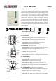

2 PL-12 User Guide AP6506 issue 1
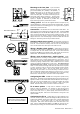
Mounting to the face plate A pre-cut brushed
aluminium wall plate is supplied according to territory, UK
(part number AA5029), EU (AA5250) or US (AA5030). A
suitable backing box for the UK plate can be ordered
(AA5220). The module fits into an ‘H’ shaped cutout in the
centre of the face plate. The module is held using the two
screws with plastic clamps provided (A). Unscrew these
from the module first. Should a custom mounting plate be
required, a template (in millimetres) is provided here.
Ensure that enough space is provided for the cables.
Safety ground Ensure that the supplied aluminium face plate (or any
custom metal plate) is correctly grounded to ensure operator safety. The plate
should be connected to a local safety ground. Use a ground wire or physical
contact with a grounded back box.
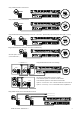
Connections Use standard one-to-one wired CAT5 / RJ45 cables. The
control of both zones is passed down a single CAT5 cable. Connect the GR2
ZONE REMOTE port to the first PL-12 TO GR2 port (CN1). If two remotes are
used, connect the first LINK port to the second TO GR2 port (CN2). Do not
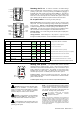
connect more than two remotes. Note the maximum cable length from the
diagram shown here. Use unbooted plugs to ensure the cables can fit into the
backing box. Allow enough service loop for module removal.
Assigning which zone to control Set the module jumper plug to
the Z1 (zone 1) or Z2 (zone 2) position. Do this while the remote power is
turned off. If two remotes are used they must not be set to control the same
zone. The first remote in the chain may be set to either Z1 or Z2.
Wiring a disable switch (option) Solder pads are provide for
connecting an external switch to disable the remote and protect the settings,
for example when the room should not be used. Such a switch could be
located near the GR2 or in the manager’s office. Each remote can have its own
disable switch. When disabled, the 4 source indicators light red.
Wiring a zone 2 follow zone 1 switch (option) Solder
pads are provided for connecting an external switch to change the operating
mode so that the zone 1 remote controls both zone 1 and zone 2. This is
useful when two rooms are used independently or combined into one on some
occasions by opening a divider screen. When combined, the zone 1 remote
controls the speakers simultaneously in both rooms. The switch must be
connected to the zone 1 remote. Connect the wires to a manually operated
switch or a micro-switch that changes state when the divider screen is opened
or closed. When the screen is open the switch contacts should be closed.
Note that setup menu option 1 may be used instead of the switch to
permanently set this mode if the one remote always controls both zones.
Option 8 determines whether follow affects the level and source, or source
only. If source only, the level can be independently set for each zone using
both remotes. If level and source, the zone 2 remote is fully disabled.
Configuring the GR2 The GR2 can be configured to operate in many
different ways. Check that its front panel DIP switches are correctly set for your
application. Make sure the remote enable switches MNOP are set according to
which zones you want the PL-12 units to control, and whether they should
work with just the level or level and source selection. Refer to user guide
AP6320. Also decide which music sources to include in the selection.
PL-12 menu options A setup menu is available to configure the
remote to match your application. For example, you may wish the source
selection to scroll between 2, 3 and 4 if you have configured the GR2 for 4
music sources with music 1 a jukebox priority source that should not be
selected on the wall plate. Refer to the menu table later in this guide on the
options available.
Configuring the PL-12 Default setting is to select between music
sources 1, 2 and 3, to power up with the last settings, the PL-5 preset store and
recall functions disabled, and the zone 2 follow zone 1 function affecting both
source and level. A good starting point is to reset the remote before
configuration. Refer to the reset and option menu instructions later in this
guide. Use the CONFIGURATION SHEET in the GR2 user guide to log your
system and option settings (can be downloaded from www.allen-heath.com).
on
PONM
remote enable
Z1 level
Z2 source
Z2 level
Z1 source
4
32
1
DISABLE REMOTE
Z2 FOLLOW Z1
CN2 CN1
TO GR2LINK
Z1 Z2
12
16
32
16
34
20
20
DIA 6
c
TOP
16
16
A
A
Note: On power up, the PL-12
firmware version number is displayed
briefly on one of the 8 level indicators.
10 100
20 80
30 60
40 40
50 20
60 m 1 m
1x PL-12 120 m
2x PL-12
MAX CABLE LENGTH