iLive Reference Guide Part 1 – Hardware Firmware Version 1.7 This guide describes the iLive system components including the many Surface and MixRack models, PL Series controllers and network card options available.
Welcome Thank you for investing in the Allen & Heath iLive digital mixing system. To get the most from your iLive we recommend you read the whole of this guide. To get started quickly refer to the Getting Started guides that come with the iLive Surface and MixRack, and then to this guide for further reference. This guide describes the iLive system components including the many Surface and MixRack models, PL Series controllers and network card options available.
Precautions Damage : To prevent damage to the equipment cosmetics, avoid placing heavy objects on the unit, scratching the surface with sharp objects, or subjecting the unit to rough handling and vibration. Environment : Protect from excessive dirt, dust, heat and vibration when operating and storing. Avoid tobacco ash, smoke, drinks spillage, and exposure to dust, rain and moisture. If the equipment becomes wet, switch off and remove power immediately. Allow to dry out thoroughly before using again.
Table of Contents Introduction ................................................................................................................ 5 Modular iLive system components............................................................................ 6 iDR10 modular MixRack ............................................................................................ 7 iLive modular Surface ................................................................................................
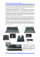
Introduction to the iLive system The modular iLive and the fixed format iLive-T and R Series provide a ‘mix and match’ system for live sound mixing. Allowing distributed control and audio over CAT5 cable, iLive is well suited to demanding live sound applications such as FOH/Monitor mixing, live recording and multi-function installed venue sound.
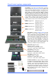
Modular iLive system components iDR10 MixRack The MixRack is the heart of the digital audio processing system. It houses the DSP mix engine together with control and audio networking interfaces. The 64 input x 32 bus architecture is fully configurable for mono/stereo and type of mix. It is known as the iDR10 because it has 10 card slots for fitting any combination of input and output modules.
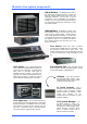
DSP ‘RackExtra’ module The DSP mix engine, the heart of the iLive mixing system. 64x32 mix architecture plus 8x internal effects. REMOTE AUDIO module With system clock, headphones and remote audio distribution. Fit up to 2 audio network option cards (RAB2 version). iDR10 Modular MixRack System modules Slots K, L, M CHK indicators Follow PAFL selection Ethernet switch 3x network ports. PP indicators Detect phantom power voltage on XLR sockets. Port A Surface and break out/in audio.
Lamp connectors Accept standard 12V console lamps. We recommend using the Allen & Heath dimmable LEDlamp. iLive Modular Surface Backup PSU input For connection to the Allen & Heath iPS10 redundant backup power supply. DC and temperature sense Audio connections XLR sockets for surface Talkback mic output, PAFL input and local monitor output. Provides an analogue alternative for connection to the MixRack when a digital audio network option is not fitted.
Fixed format system components The MixRack is the heart of the digital audio processing system, housing the 64x32 DSP mix engine together with control and audio networking interfaces. The DSP can be configured for mono/stereo and type of mix (group, aux, mains, matrix). The system provides full dynamics, EQ and delay processing for all inputs and masters, 8 built-in ‘RackExtra’ effects and 16 DCA groups. The 8FX returns add to the 64 channels providing up to 72 sources to the mix.
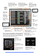
iLive Fixed Format MixRack Mic/Line inputs High performance, recallable analogue preamps for balanced or unbalanced microphone and line level signals. Gain, Pad and 48V are digitally controlled within the preamp. Digital Trim and Polarity is available within the DSP channel. Inputs are identified by Slot (card position) and Socket (number), for example A1 or C8. Any input can be patched to any DSP channel using the PREAMP screen. MIDI IN and OUT sockets.
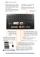
iLive T Series Surface Channel Processing Strip Analogue style control section with dedicated rotary controls, switches and meters for the channel or mix preamp, HPF, gate, PEQ, compressor and limiter/de-esser. Press the strip SEL key to access the processing of the channel or master assigned to it. The controls illuminate when they are available. TouchScreen For status display, system setup and memory management.
iLive R72 Surface TouchScreen keys When these keys are off the screen displays system status. When these keys are off and a strip SEL is active the screen presents the associated channel processing. Use these keys to access system setup and memory management. These override the channel processing view. Soft Keys 8 user assignable keys Channel Processing Select Press this key to access the processing for the selected channel using the TouchScreen.
Connecting the modular iLive MixRack and Surface The iLive has two main system connections between the Surface and MixRack, both using CAT5 cables. NETWORK is the control interface to the MixRack. Port A primarily connects audio to and from the Surface and other EtherSound equipped break in/out devices. The optional Port B can be used to connect audio between systems such as FOH/Monitor, broadcast or recording. iLive systems are shipped with 1.
Using ACETM This requires a single CAT5 cable which transports AUDIO and CONTROL over the same cable. Plug MixRack Port A ACE 1 to the Surface Port A ACE 1 to connect the PAFL, talkback and rear panel input/output signals (channels 1 to 32) to and from the Surface. For information on using the optional network modules refer to information later in this user guide.
An IEC mains power cord with moulded plug suitable for your territory is provided for each power supply module within the system. The iLive system uses universal voltage power supplies that accept world wide mains sources from 100 to 240V.AC 47 to 63Hz. Make sure the IEC plugs are pressed fully into their panel sockets and the cables are clipped into the retaining clips to protect them from accidental disconnection.
Connecting the fixed format MixRack and Surface The Control Surface If the system fails to connect: Check cables, Go to Network Connections and Change MixRack Read the Help Manual. Connect Surface to MixRack Network settings Plug a CAT5 cable up to 120m * (400 feet) between the Surface and MixRack ACE ports. iLive communicates over a TCP/IP network. There are 3 main components – the MixRack, Surface and TouchScreen (built into the surface).
Turning on the system Turning on the system The iLive system remembers its last settings on power up. 1. 2. 3. First, plug in the mains and CAT5 cables. Next, switch on the MixRack power. Then switch on the Surface power. While searching for the network connection between the MixRack and Surface after power up, the NETWORK Lnk/Act indicators flash at a slow rate for a few seconds. Once connection is successfully made the indicators flash at a steady fast rate.
Surface Audio connections T Series Surface audio connections While the iLive surfaces feature a built-in modular audio card frame, the lower cost T Series presents a fixed format audio interface for input and output connections. This matches the typical requirement for audio local to the surface. iLive surface 4 slots for audio modules. 8 inputs or outputs per card. Up to 32 connections. Capable of mic, line or digital signals. Port A - Surface to MixRack audio link. Choose option.
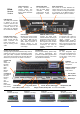
iLive Module options – Analogue inputs and outputs MIC/LINE Input part M-MICIN-A This is the main audio input module for the iLive system. It provides 8x high performance analogue input preamps for microphone and line level signals. The front end gain, pad and phantom power are remote controlled via the network connection from the Surface or PC. The settings may be recalled as part of the iLive system memories. CHK Yellow indicator follows the PAFL function.
Module options – Digital inputs and outputs DIGITAL INPUT part M-DIGIN-A This module provides 8 digital inputs arranged as four pairs. Each offers a choice of digital format - AES, SPDIF or optical (TOSLINK). For each pair, one format is chosen and used at a time. The selection is made using the iLive Surface or PC application channel SEL function. One of 3 yellow LED indicators lights to show which input format is selected.
Module options – Digital outputs DIGITAL MULTI OUT part M-MULTI-OUT-A This module provides 16 outputs and therefore uses two slots at the MixRack or Surface. Use the iLive OUTPUTS patch bay to map any signal to any output socket. The module presents these outputs simultaneously to a variety of different multi-channel digital formats: ADAT There are two ADAT optical light pipe outputs, each carrying 8 audio channels. Use these to connect to ADAT equipped devices such as multitrack recorders.
Module options – MixRack system CPU module Provides the control interface to the MixRack. This module is identified as the ‘iDR RACK CPU’. It is not interchangeable with the iLive Surface CPU module. Power ON Blue LEDs display the power supply status. One or two power supply modules may be fitted to the MixRack. The second provides dual supply redundancy. 12V LAMP Plug in a standard 4-pin XLR gooseneck console lamp to illuminate the rack while plugging up in a dark environment.
Module options – MixRack system These 3 modules make up the ‘brains’ of the iLive mix system. They process the audio, control the system and handle digital audio distribution to and from the Surface and other equipment. iDR-64 RackExtra DSP This is the DSP mix engine, the ‘brains’ of the iLive system. The DSP (Digital Signal Processing) handles the audio signal processing such as EQ, dynamics, delays and mixing.
Module options – the RAB2 module The REMOTE AUDIO 2 (RAB2) module is the latest version of the digital audio networking module available for the iDR10 and iDR0 MixRacks and iLive-80, iLive-112, iLive144, and iLive-176 Surfaces. The module manages the system audio clocks and also provides multi-channel digital audio networking and interface capability.
Module options – Surface system iLive Surface system modules These are the modules required to manage the iLive modular Surface and handle the control and digital audio interface ports. Internal power supply Connection for optional iPS10 backup power supply iLive Surface CPU module (always fitted) This is the controller module for the iLive Surface. It houses the NETWORK and other interfaces used to control the MixRack. The iLive MixRack and Surface use different versions of CPU module.
Module options – Digital audio networking cards These are ‘mini’ module options available to interface with popular multi-channel digital audio and networking standards. They may be fitted to: iDR10 and iDR0 RAB2 module Port A and Port B. iDR-64, iDR-48, iDR-32 and iDR-16 Port B iLive-80, 112, 144, 176 RAB2 Port A, only MMO in Port B. They may not be fitted to the R72, T80 or T112 Surfaces.
ACE card instructions Part number M-ACE-A M-ACE is one of several plug-in card options that may be fitted to the iLive Series. It can provide a multi channel digital audio and network control link between two MixRacks or between a MixRack and Surface using a single CAT5 cable. ACE offers an alternative to EtherSound and other networking standards providing a digital audio snake for situations where point-to-point rather than distributed network connection is required.
FOH SYSTEM MONITOR SYSTEM T Series Surface ACE T Series Surface ACE control audio control audio iDR-48 iDR-32 Port B ACE control audio Tunnel another TCP/IP network through ACE You can use the Bridge socket to transport a non-related 3rd party TCP/IP network such as a lighting or amplifier system controller. Make sure their IP addresses do not conflict with those of the iLive systems.
Cable and connectors A&H part AH7001 A&H part AH7000 Standard 1.8m 80m drum ACE is compatible with CAT5e T568A and T568B twisted pair cable standards. For on the road reliability and protection choose a heavy duty touring grade cable type. Maximum length = 120m (400 feet) depending on cable type. Most good quality CAT5 cables should work reliably to around 40m (130 feet). We do not guarantee that all cable types will work reliably at longer lengths.
EtherSound card instructions – ES V2 complete Part number M-ES-V2-A M-ES-V2 is one of several plug-in card options that may be fitted to the iLive Series. It houses the Auvitran AVDM card to provide a multi channel digital audio network that can link iLive MixRacks and Surfaces, transport and split signals between systems and distribute audio around a venue using CAT5 cables. Note 1 To fit to the iDR10 and iLive Surfaces, the Remote Audio 2 (RAB2) module is required.
EtherSound card instructions – ES V1 base Part number M-ES-V1-BASE-A M-ES-V1-BASE is a carrier frame that lets you re-use the original Auvitran AVD EtherSound card option from the earlier Remote Audio (RAB) module when upgrading to the more recent Remote Audio 2 (RAB2) module. The RAB2 module is available as an upgrade for existing users who want to benefit from the wide range of audio interface options now available for iLive.
Installing ES-V1 in RAB2 Step 1 Fit the carrier frame into the RAB2 module Remove the RAB2 module from the MixRack or Surface. Unscrew and remove the option slot blanking plate. Use Port A (the top option slot) if you want to use EtherSound as the Surface to MixRack link. Use Port B (the lower option slot) for system expansion, digital mic splitting and signal distribution. Note Make sure the EtherSound card is not fitted to the carrier at this stage.
MMO card instructions Part number M-MMO-A The Mini Multi Out (MMO) module is one of several plugin card options that may be fitted to Port B in the iLive system. It provides three formats of multi-channel digital output simultaneously available for recording, personal monitoring and signal distribution. Note: The MMO module is supported from iLive firmware V1.5 onwards. Please refer to www.allen-heath.com for the latest version.
Patching signals to MixRack Port B iLive recognises the type of option card fitted to Port B of the MixRack. Use the TouchScreen or Editor OUTPUTS screen Port B tab. You can assign one or a range of signals to the different outputs by touching the output you want to assign and choosing selections from the drop down menu. Touch Apply to confirm the selection. The input and output patching including Port B is archived within the Show memories and can be stored in the Scenes ‘Patchbay’ item.
MADI card instructions M-MADI is one of several plug-in card options that may be fitted to the iLive Series. It provides a multi channel digital audio network that can distribute signals between iLive and 3rd party MADI equipment. MADI offers an addition or alternative to EtherSound and other networking standards available for the iLive system.
MADI Operating modes Dual Link mode The card supports two separate MADI BNC links letting you connect to two separate devices simultaneously. Make sure the MIXER SETUP / Mixer Pref screen Redundant Link Option is set to ‘Off’. Sources to the iLive channels can be patched from either LINK 1 or LINK 2 MADI stream in blocks of 8. First, use the MIXER SETUP / Mixer Pref screen to set up which MADI link is made available as a selectable source to the blocks of 8 iLive channels.
iDR-8, iDR-4 and PL Series remote controllers iDR Mix Processors The iLive integrates easily with the Allen & Heath iDR-8 or iDR-4 rack mounted mix processor via the M-MULTIOUT or M-MMO modules. This provides the convenience of a single CAT5 cable up to 250m long to transport 8 signals from the iLive. The iDR mixers are ideal for installed sound system and speaker management. iDR Expanders These are 1U rack mounted 8 channel output expanders.
Other components available iLive Editor software The Editor application runs on a PC or MAC computer to control the iLive system via Ethernet. Editor is compatible with both the iLive and the T Series and can be downloaded free of charge from the Allen & Heath web site. Download either the PC or MAC version. The version number of Editor and the firmware running in the iLive must be compatible. Editor should always be updated when the system firmware is updated.
Modular iLive dimensions and weights iPS10 PSU / iDR0 MINIRACK 643 mm / 25.3" 669 mm / 26.34" 482 mm / 19" 88 mm / 3.46" MIXRACK FLIGHT CASE 730 mm / 28.75" FRONT ALLEN HEATH 443 mm / 17.4" 142 mm / 5.6" 2U REAR 374 mm / 14.7" 310 mm / 12.2" SIDE MIXRACK IN FLIGHTCASE = 68kg / 150lb MIXRACK IN CARTON = 27kg / 60lb iPS10 = 7kg / 15lb iDR0 = 7.3kg / 16lb iPS10 IN CARTON = 8.5kg / 19lb iDR0 IN CARTON = 9.3kg / 21lb 353 mm / 13.9" iLIVE SURFACE ALLEN&HEATH Mains cord clip iLive-80 753mm / 29.
iLive-80 = 860mm / 33.9" iLive-112 = 1109mm / 43.7" iLive-144 = 1309mm / 51.5" iLive-176 = 1509mm / 59.4" SURFACE FLIGHT CASE 452 mm / 17.8" 152 mm / 6" 1017 mm / 40" ALLEN HEATH iLive SURFACE IN FLIGHTCASE = iLive-112 98kg / 216lb SURFACE IN CARTON = iLive-80 39kg / 86lb iLive-144 114kg / 251lb iLive-176 124kg / 273lb ALLEN&HEATH iDR-64 MIX ENGINE SIDE 350 mm / 13.8" FRONT 400 mm / 15.75" 9U iDR10 MIXRACK 482 mm / 19" 44 mm / 1.73" 582 mm / 22.9" 707 mm / 27.
Fixed format iLive dimensions and weights T112 SURFACE T112 WEIGHT = 27kg / 59.4lbs T80 WEIGHT = 20kg / 44lbs 1083mm / 42.6" 46mm / 1.8" 280mm / 11" T80 SURFACE 620mm / 24.4" 768mm / 30.2" 635mm / 25" DEPTH 250mm / 9.9" DEPTH 300mm / 11.8" 8U iDR-48 9U iDR-64 132mm / 5.2" iDR-16 iDR-32 265mm / 10.4" 6U 482mm / 19" 3U DEPTH 250mm / 9.9" 353mm / 13.9" iDR-16 WEIGHT = 7.5kg / 16.5lbs iDR-32 WEIGHT = 11.5kg / 25.3lbs iDR-48 WEIGHT = 14.5kg / 31.9lbs iDR-64 WEIGHT = 17.5kg / 38.
iLive-R72 rack ear fitting instructions Desk Top - Side Trims Fitted 237mm (9.33") 1 To fit rack ears Remove 8x M4 x 8mm TORX screws Use T20 driver 172mm (6.77") 120.7mm (4.75") 52.5mm (2.07") 368mm (14.5") 482.2mm (19") 540mm (21.26") from front of trim Rack Ears - Flush Mounted M6 x 16mm SLOT screw part AB0344 3 217mm (8.54") M6 cup washer part AB0345 12U Two rack ear positions are available – either flush with the control panel or angled at 16 degrees for a lower profile fit. 13U 131mm (5.
Limited One Year Manufacturer’s Warranty This product is warranted to be free from defects in materials or workmanship for period of one year from the date of purchase by the original owner. To ensure a high level of performance and reliability for which this equipment has been designed and manufactured, read this User Guide before operating. In the event of a failure, notify and return the defective unit to the place of purchase.