iLive Fixed Format Systems Getting Started Guide Publication AP7141 This guide is intended to help the new user quickly learn to configure and operate the fixed format iLive audio mixing system. Fixed format and modular iLive components are fully compatible with each other letting you mix and match any combination of MixRack and Surface according to application and budget.
Safety Instructions Before starting, read the Important Safety Instructions printed on the sheet supplied with the equipment. For your own safety and that of the operator, technical crew and performers, follow all instructions and heed all warnings printed on the sheet and on the equipment panels. System operating firmware The feature set of the iLive is determined by the firmware (operating software) that runs it.
Table of Contents Introduction ............................................................................................................................................... 5 System components .............................................................................................................................. 6 T Series control layout ......................................................................................................................... 7 R Series control layout.................
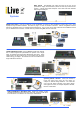
Basic system The MixRack (mix engine and most of the I/O) can be positioned on stage, and the Surface (control and local I/O) at the FOH mix position. A single CAT5 cable transports control and local audio between them using the ACE port. Systems Adding more control Plug into a Network port at the MixRack or Surface to add simultaneous control using one or more laptops running iLive Editor software. Use wired or plug in a router for wireless connection.
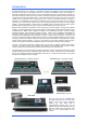
Introduction The fixed format iLive is an evolution of the flagship modular iLive digital live mixing range with all the performance and power of its bigger brother in a compact and affordable, easy to use package. It separates the DSP mix engine from the control surface allowing the rack to be positioned on stage and the surface at the FOH (front of house) mix position, linked by a single long distance CAT5 cable carrying control and local FOH audio between them.
System components The MixRack is the heart of the digital audio processing system, housing the 64x32 DSP mix engine together with control and audio networking interfaces. The DSP can be configured for mono/stereo and type of mix (group, aux, mains, matrix). The system provides full dynamics, EQ and delay processing for all inputs and masters, 8 built-in ‘RackExtra’ effects and 16 DCA groups. The 8FX returns add to the 64 channels providing up to 72 sources to the mix.
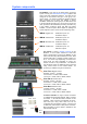
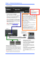
T Series Control layout Channel Processing Strip Analogue style control section with dedicated rotary controls, switches and meters for the channel or mix preamp, HPF, gate, PEQ, compressor and limiter/de-esser. Press the strip SEL key to access the processing of the channel or master assigned to it. The controls illuminate when they are available. TouchScreen For status display, system setup and memory management.
iLive-R72 Control layout TouchScreen keys When these keys are off the screen displays system status. When these keys are off and a strip SEL is active the screen presents the associated channel processing. Use these keys to access system setup and memory management. These override the channel processing view. Soft Keys 8 user assignable keys Channel Processing Select Press this key to access the processing for the selected channel using the TouchScreen.
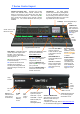
Step 1 – Connect and power up The Control Surface If the system fails to connect: Check cables, Go to Network Connections and Change MixRack Read the Help Manual. Connect Surface to MixRack Network settings Plug a CAT5 cable up to 120m * (400 feet) between the Surface and MixRack ACE ports. iLive communicates over a TCP/IP network. There are 3 main components – the MixRack, Surface and TouchScreen (built into the surface).
Switch power on Switch on the MixRack first, then the Surface by pressing their rear panel power ON switches. The system remembers the settings on power down. These are restored next time you switch the system on. Boot up time Secure the mains cable in the clip provided here. The yellow Lnk/Act LEDs for connected sockets flash at a steady rate once the link is established.
Step 2 – Recall a ‘Template Show’ as a starting point The iLive has a fully configurable audio architecture and control layout and socket patching letting you customise the way you work. It would be a daunting task for the new user if we gave them a ‘blank canvas’ to start from scratch. Instead we have provided a set of ‘Template’ Show memories which give you a choice of classic console format to load in as a quick starting point.
Step 3 – A few things to know before starting Before working with the iLive familiarise yourself with its control layout and operating principles. Two important keys SEL PAFL MUTE MIX SEL - Select the channel processing. View and adjust the parameters for that channel. Within the processing section use these keys to open individual processing blocks on the screen, or press and hold to send the signal at that point to the PAFL system.
Set your operating preferences PAFL – Choose: Additive or auto cancel mode when you press more than one PAFL key. Options for the MIX and SEL keys to follow PAFL key presses. For example, pressing a single key can route the signal to the PAFL monitor, open its channel processing and present its mix and assignments on the strips. PFL level trim balance relative levels between PFL and AFL. Main mix to PAFL monitor level. Set to ‘-inf’ (off) to silence the monitor when no PAFL is selected.
Step 4 – Name and colour channels Having chosen a Template show as your starting point, and set your operating preferences, you may wish to prepare for your show by naming your inputs, mixes and DCAs, and applying colour to help identify them by type or to highlight important channels. You can name channels with up to 5 characters entered from an on-screen touch keyboard. You can colour each or ranges of channels with one of 6 colours or no colour.
Step 5 – Work with the channel processing Channel Processing Block SEL PAFL MUTE MIX * Processing SEL keys Due to its compact size, the smaller iLive surfaces do not provide all the physical controls. Access these parameters using the TouchScreen. Access the Preamp, EQ and dynamics Press a strip SEL key. Press the key again to turn it off or press another to access a different channel.
Step 6 – Work with the mix SEL PAFL MUTE Press a strip MIX key. The current mix status is displayed in the lower part of the strip LCDs. Mix sends are presented on faders or encoders. The current mix selected is displayed in the lower status bar of the screen. MIX Note – Make sure you are working with the correct mix. After making your adjustments remember to turn off the MIX key or return to your main mix. Turning off the MIX key automatically returns to the main mix.
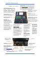
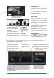
Channel MIX view - Sends to all masters from one channel STEREO MASTERS AUX CHANNEL IEM1 PAN L IP R AUX LEV 1 CH FADER STEREO AUX STEREO AUX AUX WDG1 WDG2 IEM1 AUX PRE PAN IEM2 PAN L R CH FADER PAN L PRE 5 R PRE L R PRE PRE ROTARY SHIFT SEL PRE/POST FADE MIX ASSIGN 3 SEL SEL SEL SEL MIX MIX MIX MIX Current mix status ON = channel is assigned PRE = Channel send is set prefader.
Work with the FX iLive works with FX in a similar way to analogue consoles, using a send and return path, for example reverb or delay effect. You can also configure inserted effects such as a flanger or reverb on a single channel. Spatial Modelling Reverberator Gated Reverb Inserted FX Patch the FX unit into a channel or mix 2 Tap Delay master signal path.
Using DCA groups A DCA is the digital equivalent of the analogue console VCA group. iLive features 16 DCA groups. To assign channels to a DCA group, select the DCA master MIX key. Hold down ASSIGN and press channel MIX keys to toggle ON or off. Alternatively open the DCA master ROUTING screen using its SEL key. Note - Make sure you turn off the DCA master MIX key or select your usual MIX after you have finished assigning the groups.
Channel Ganging Ganging lets you link selected processing and mix parameters between input channels or masters, for example the EQ, gate and compressor of a stereo keyboard, or the GEQ of the L and R main mix. Ganging does not include the input Preamp (gain). SEL PAFL MUTE To enter Ganging Setup mode and view and assign ganged input or mix master channel parameters, select the TouchScreen MIXRACK / Ganging page. MIX Ganged channels must be compatible input or mix types.
Step 7 – Patch the sockets The iLive features a built-in soft patchbay that lets you freely patch input and output sockets. The default Template Shows provide a standard patch as a useful starting point. You can change this patching to suit your application and store it in the Scene and Show memories. View and patch channel INPUT sockets Press SEL for an input channel and view its screen PREAMP page (Make sure the keys next to the TouchScreen are turned off).
Step 8 – Customise your configuration Once you have familiarised yourself with the operation of the iLive through using a Template Show, you may wish to take advantage of its unique flexibility by reconfiguring the channel and master strip layout, DSP mix bus and stereo channel architecture, soft key assignments and more. You can ‘design’ your own console to suit the way you like to work. Note - These instructions are intended to get you started.
Step 9 - Save your settings iLive provides different types of memory to store your settings. Back up your settings to the onboard memories or archive them to your PC via USB key. For more information refer to the on screen HELP manual. Power down memory You do not need to store settings before switching the system off. iLive remembers its last settings on power down and restores these when the system is next turned on. Your settings are restored even if mains power is lost without warning.
Scene memories iLive has 250 Scene memories. These are 'snapshots' of all or a selection of the live mixing parameters. They do not store the DSP bus configuration and user preferences. Before starting go to the SURFACE / Preferences screen and set the options to enable or disable the Scene Up/Down/Go keys, and turn on or off the Scene Editing Confirmation popup box. For the most secure operation we recommend that you disable these keys and turn on the confirmation popups. Select the SCENE screen.
Scene Recall Safes lets you make selected input channels, mix and DCA masters 'safe' so that their parameters are not overwritten when a Scene is recalled. Hold down the SCENE SAFES key and press the strip MIX keys on channels you want to make safe. The SAFE icon in the strip LCDs turns on for channels made safe. Preamp Safes The mic preamp is automatically included in channels made safe.
Dual-Rack input expansion Two MixRacks may be connected in Dual-Rack mode to expand the number of input channels from 64 to 128. The number of physical inputs available depends on which MixRacks are used. This does not expand the number of mix buses. Step 1: iLive Surface Important note: The Master and Slave MixRacks must have unique IP addresses and Unit Names. iLive-R72 iLive-T80 Make sure both addresses and names have been set before the two MixRacks are connected together.
System example The following is just one of many system combinations possible with iLive. Here, two MixRacks are linked for digital mic split from one set of preamps feeding two independent mixers, one for FOH, the other for on-stage monitors. One engineer uses a compact T80 Surface to mix the house sound, the other uses a wireless laptop to mix monitors on stage.
iLive-R72 Rack Ears - Fitting Instructions Desk Top - Side Trims Fitted 237mm (9.33") 1 To fit rack ears Remove 8x M4 x 8mm TORX screws Use T20 driver 172mm (6.77") 120.7mm (4.75") 52.5mm (2.07") 368mm (14.5") 482.2mm (19") 540mm (21.26") from front of trim Rack Ears - Flush Mounted M6 x 16mm SLOT screw part AB0344 3 217mm (8.54") M6 cup washer part AB0345 12U Two rack ear positions are available – either flush with the control panel or angled at 16 degrees for a lower profile fit.
Fixed Format iLive - Factory Default Show Template Show = FOH-LRSub Bus configuration LRSub main mix 4 mono, 2 stereo Groups 8 mono, 2 stereo Auxes 6 mono FX sends 4 mono, 2 stereo Matrix 16 DCAs Channels FX CH1 - 60 = mono CH61/62, 63/64 = stereo 6 Send/Return stereo FX 2 insertable stereo FX Layout assigned for - 40 MixRack mic inputs + 4m/2st Surface inputs L, R, Sub main mix, 2m/2st Groups, 6m/2st Auxes, 4 FX, 2m/2st Matrix You can change your configuration and layout to suit your application Name
System Format DSP Audio Network Port A Audio Network Port B Con trol Network PL-Anet MIDI USB VGA Mains Power Separate MixRack and Surface with control & audio over a single CAT5 ACE™ cable 64x32 RackExtra DSP mix engine located in MixRack Local audio to/from Surface - ACE™ up to 120m CAT5 (depending on cable)* Network option plug-in cards available - see website for details TM TCP/IP Ethernet (links to Surface via Port A ACE ), built-in switch At MixRack for A&H PL Series remote controllers and GPIO In/O
iLive Fixed Format Getting Started Guide 31 AP7141 iss.
Limited One Year Manufacturer’s Warranty This product is warranted to be free from defects in materials or workmanship for period of one year from the date of purchase by the original owner. To ensure a high level of performance and reliability for which this equipment has been designed and manufactured, read this User Guide before operating. In the event of a failure, notify and return the defective unit to the place of purchase.