0L[:L]DUG#6HULHV :=47=7=5.
LIMITED ONE YEAR WARRANTY This product has been manufactured in the UK by ALLEN & HEATH and is warranted to be free from defects in materials or workmanship for period of one year from the date of purchase by the original owner. To ensure a high level of performance and reliability for which this equipment has been designed and manufactured, read this User Guide before operating.
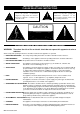
IMPORTANT SAFETY INSTRUCTIONS PLEASE READ THESE INSTRUCTIONS This symbol, wherever it appears, alerts you to the presence of uninsulated dangerous voltage inside the enclosure that may be sufficient to constitute a risk of electric shock. This symbol, wherever it appears, alerts you to important operating and maintenance instructions in the accompanying literature. Please read the operating instructions.
x OBJECT & LIQUID ENTRY: Care should be taken so that objects do not fall and liquids are not spilled into the enclosure through openings.
INTRODUCTION The WZ14:4:2 continues ALLEN & HEATH’s commitment to providing high quality audio mixing consoles engineered to meet the exacting requirements of today’s audio business. It brings you the latest in high performance technology and offers the reassurance of over two decades of console manufacture and customer support. This user guide presents a quick reference to the function and application of the WZ14:4:2. We recommend that you read this guide fully before starting.
[#: :L]DUG#47 47==7=5 OVERVIEW OF THE 0L[# The WZ14:4:2 combines uncompromised features with impressive performance for live sound engineering and recording. Built on the established tradition of innovative British design and manufacture, WZ14:4:2 is solidly reliable for a hard life on the road and uniquely versatile for any audio mixing application.
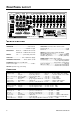
FRONT PANEL LAYOUT 5 0 -5 PAD -30dB 40 50 PAD -10 -5 1kHz OSC PINK NOISE 20 ON GAIN POWER ON 15 -10 20 MIC IN 10 GAIN 40 30 GAIN 15 PAD -30dB 30 5 0 10 GAIN TALKBACK TRIM OSC/NOISE TRIM ON 50 - 10 20 60 30 - 10 20 60 30 5 0 100Hz 0 100Hz 10 -5 + 15 -15 3kHz 5k 700 7k 500Hz 15kHz 0 -5 1k GROUP 15 AUX 700 15kHz 0 -10 45 450 1kHz 0 -15 + 15 ON MONO MONO 0 HF -15 45 1kHz OSC/PINK NOISE -15 + 15 0 MF1 ! 1kHz 0 -15 + 15 + 15 -15 -15
REAR PANEL LAYOUT OUTPUTS STEREO INPUTS 2-TRACK RETURN 13-14 SEND L L R R INSERT L INSERT 3 1 IN MIC/LINE INPUTS A IN L A5 A3 A1 OUT OUT OUT M 10 9 8 7 6 5 4 3 2 1 INSERT INSERT INSERT INSERT INSERT INSERT INSERT INSERT INSERT INSERT 11-12 INSERT A L R R IN L/M B IN L/ M R R B IN IN IN IN IN IN IN IN IN IN 10 9 8 7 6 5 4 3 2 1 DIR OUT 10 DIR OUT 9 DIR OUT 8 DIR OUT 7 DIR OUT 6 DIR OUT 5 DIR OUT 4 DIR OUT 3 DIR OUT 2 DIR OUT
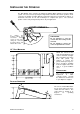
INSTALLING THE CONSOLE The Mix Wizard Series features the ALLEN & HEATH Quick Change Connector (QCC) system. The rear connector pod may be hinged and locked into either of two positions: Rear connectors for desktop operation with the control panel sloped at a convenient 15 degrees, or underside connectors for 19" rack mounting in a compact 10U space. The connector position can be easily changed at any time to fit your application.
CONNECTING MAINS POWER TOREDUCE THERISK OF FIRE OR ELECTRIC SHOCK DONOT EXPOSETHIS APPARATUS TORAIN ORMOISTURE. WARNING- THIS APPARATUS MUST BEEARTHED. SUPPLY VOLTAGE RANGE: CAU TION AC MAINS IN ~ 100 - 240V ~ 47-63Hz ~ 30WMAX OFF ON AVIS: RISQUE DECHOC ELECTRIQUE- NEPAS OUVRIR. 100 - 240V~ FUSE T500mA 250V 20mm WARNING: FORCONTINUED PROTECTION AGAINSTRISK OFFIRE REPLACEFUSE WITH SAMETYPE AND RATING ATTENTION: REMPLACERLEFUSIBLEAVEC UN DES MEMES CARACTERISTIQUES.
PLUGGING UP THE SYSTEM The Mix Wizard 14:4:2 uses professional grade 3-pin XLR, 1/4" TRS jack and RCA PHONO sockets. The applications diagrams on pages 19 to 21 illustrate typical equipment interconnections. To ensure best performance, we recommend that you use high quality audio cables and connectors, and take time to check for reliable and accurate cable assembly. It is well known that most audio system failures are due to faulty interconnecting leads.
PLUGGING UP THE SYSTEM (CONT’D) CONNECTING CHANNEL INPUTS (CONT’D) CONNECTING TO CHANNEL INSERTS You do not need to plug anything into the channel insert socket for normal operation. You may, however wish to insert a signal processor such as a compressor/limiter or noise gate into the channel signal path to prevent excessive peaks or to cut down source noise. The insert lets you do this by breaking the signal path after the input pre-amp and before the EQ.
PLUGGING UP THE SYSTEM (CONT’D) L-R MIX INSERTS Operation is identical to channel inserts. Use these sockets if you wish to insert external signal processing equipment into the mix pre-L-R fader. For live sound it is common to insert graphic equalisers to adjust for the room acoustics. Use a suitable Y-adapter lead as illustrated on page 12 : tip = send, ring = return. GROUPS Groups 1-4 are output to 3-wire balanced XLR connectors to drive long cable runs. Inserts are provided as for the L-R outputs.
MONO INPUT CHANNEL PAD - Attenuates the input signal by 30dB. It affects both the XLR and jack inputs. Press this switch when the input signal is too high with the GAIN control backed off.
STEREO INPUT CHANNEL 5 0 GAIN 10 -5 15 -10 20 ON 5 0 10 GAIN -5 15 -10 20 ON MONO 0 HF -15 + 15 0 -15 + 15 0 MF2 -15 + 15 0 LF 60Hz -15 + 15 EQ IN AUX 1 0 OO +6 AUX 2 0 OO +6 AUX 3 0 OO +6 AUX 4 0 OO +6 POST PRE AUX 5 0 OO +6 AUX 6 0 OO +6 POST PRE BAL L R ODD EVEN ON PEAK GAIN A - Use this control to adjust the channel input sensitivity to match the connected source (-20 to +10dBu) to the console operating level (0dBu) on the RCA Phono connectors.
GROUP/AUX OUTPUT GROUPS Group outputs are controlled by 100mm travel faders which offer a further 10dB boost above the normal ‘0’ dB operating level. ON switches the group output on or off. AFL (After Fade Listen) routes the post fader signal to the console meters and headphone monitoring to allow checks for sound quality and mix level. The AFL signal is sourced before the ON switch allowing the signal to be checked even when the group is switched off.
MASTER & MONITOR MAIN L-R OUTPUTS POWER ON 5 4 4 6 3 7 2 3 9 SEND 0 6 7 2 8 1 5 8 1 9 10 0 RETURN 10 L-R 2-TRACK REPLAY + 16 +9 L-R FADERS - Individual 100mm faders adjust the main L-R mix level with +10dB boost available above the nominal ‘0’ position. For best performance the faders should be operated around the ‘0’ position for normal ‘loud’ level.
SETTING UP THE SYSTEM The WZ14:4:2 Master Section oscillator section provides for two modes of operation: TONE Mode – A pure 1kHz tone, used for setting up input levels on external devices, such as recording equipment, FX processors and so on. Pink Noise Mode – A ‘pink noise’ signal, which is the standard signal-type used by acousticians for setting up speaker systems, checking for faults in phase, drivers, crossovers etc.
FRONT OF HOUSE Live bands, Theatre, Church, Disco, Club, etc... MONO 2 1 4 3 TWO TRA CK REC ORDER L R 6 FOLDBAC K 5 M O NO L R play record groups pre -fade aux sends EFFECTS PRO CESSOR insert EFFECTS returns Pos t-fade r aux sends TW O TR ACK REC ORDING AND INT ERM ISSION REPLAY U se the console tw o track send a nd re turn so ckets for connecting a cassette or D AT recorde r. A lterna tively, connect a C D player to th e co nsole tw o track re turn sockets for interm issio n replay.
STAGE MONITOR On stage mixing system for local (side of stage) control of performers monitor loudspeakers (wedges) with dedicated output for monitor engineer’s listen wedge. STAGE MONITORS 1 6 2 5 3 mic splitter 4 AMPLIFIERS ENGINEER'S WEDGE MONITOR Set up the WEDGE MIX by selecting one or a combination of the groups/L-R AFL switches to listen to the desired monitor outputs. These are post insert and therefore post graphic EQ and post fader for accurate monitoring.
DUAL MODE Left , Centre and Right Front of house system with 4 dedicated stage monitor sends LEFT RIGHT MONO 3 4 STAGE MONITOR 1 2 STAGE MONITOR MONO LR groups 1-4 stereo returns 1-2 EFFECTS SIGNAL PROCESSOR aux 5-6 inserts GRAPHIC EQUALISERS Graphic equalisers plugged into the console inserts are an invaluable aid to reducing on-stage acoustic feedback and enhancing the clarity of the monitors.
CUE SHEET – Copy and use this sheet to record mixer settings 0L[:L]DUG 5 0 -5 PAD PAD -30dB 40 30 50 PAD 50 PAD - 10 20 60 30 50 PAD - 10 20 60 30 50 PAD - 10 20 60 30 50 PAD - 10 20 60 30 50 PAD - 10 20 60 30 50 PAD - 10 20 60 30 50 PAD - 10 20 60 30 -30dB 40 30 GAIN 50 PAD - 10 20 60 30 -10 GAIN 100Hz 0 HF 0 HF 12kHz + 15 0 HF 12kHz -15 100Hz + 15 0 HF 12kHz -15 3kHz 100Hz + 15 0 HF 12kHz -15 3kHz 100Hz + 15 0 HF 12kHz -15 3kHz
OPTIONS The Mix Wizard Series WZ14:4:2 has a versatile architecture designed to satisfy your live sound and recording requirements without modification. The following internal options are offered to provide alternative settings for those applications which may demand them. These options require resoldering of circuit board links and should only be carried out by competent technical personnel. Further information is available from your service agent or the WZ14:4:2 SERVICE MANUAL.
L R GRP 1-4 AUX 1-6 PFL/AFL 0L[:L]DUG 47=7=5.