
Operation Manual


Allen & Heath 16 WZ
4
16:2 and 12:2 User Guide
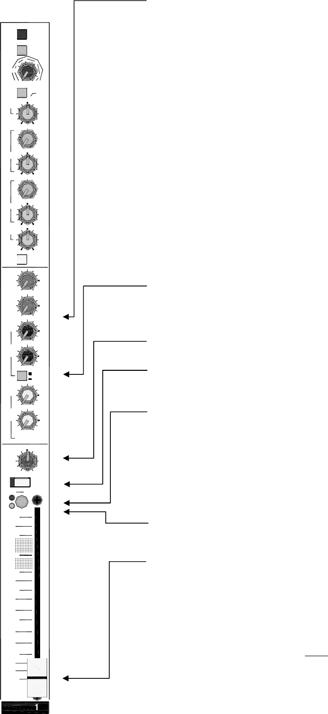
AUX SENDS These rotary controls adjust how much channel signal is
mixed to the aux outputs. Each of the 6 auxes has its own control. They
adjust from fully off to +6dB boost. Unity gain 0dB is marked at 3 o’clock
position. Factory default settings should satisfy the most common applica-
tions:
AUX1, AUX2 = Pre-fade
AUX3, AUX4 = Switched pre/post using PRE switch
AUX5, AUX6 = Post-fade
Pre-fade aux options: Pre-INSERT, pre-EQ, post-MUTE
These settings may be changed if preferred by repositioning internal jumper
link / solder link options. They offer many different combinations of pre and
post-fade sends, and a post-EQ option for the pre-fade sends. The PRE
switch can be assigned to one, two or more of the sends. More detail is
provided in OPTIONS later in this guide.
Pre-fade aux sends are not affected by the channel fader movements. These
are typically used to feed stage monitors. In most cases users also prefer
that the monitor sends are not affected by inserted processors or the chan-
nel EQ. Post-fade aux sends follow the channel faders and are typically used
to send a proportion of the channel signal to an effects device such as reverb
or delay. Pre or post-fade sends may also be used for special applications
such as recording, zone feeds, clean feeds and aux fed subs.
PRE When pressed the pre-fade channel signal is sent to the associated
auxes. When released the post-fade signal is sent. Auxes 3 and 4 are affect-
ed by the PRE switch (factory default). You can change this to dedicated pre
-fade using the internal options.
PAN Positions the channel signal between L and R in the stereo mix. The
centre position (mono image) is detented for quick resetting.
MUTE When pressed the channel signal is turned off. This affects the feed
to the LR mix, pre and post-fade aux sends and direct output, but does not
affect the insert send. The red indicator lights when the channel is muted.
PFL Press PFL to listen to the pre-fade channel signal in the headphones or
AB monitor (if configured) without affecting the main outputs. The console
main LR meters are interrupted with the channel signal. The red PK indica-
tor half lights to show that PFL has been selected on that channel. Selecting
more than one PFL at the same time mixes those signals together in the
monitor.
PEAK The red indicator illuminates when the channel pre-fade signal is
within 5dB of clipping. This gives you enough warning to reduce the GAIN
control before you hear signal distortion.
SIGNAL The green signal presence indicator lights when the channel pre-
fade signal is greater than -12dBu.
FADER Controls the channel level feeding the main LR mix and post-fade
aux sends. It also affects the direct output if this has been set to post-fade
using the internal option jumper. The fader provides +10dB maximum boost
above its normal unity gain 0dB position.
Important note on setting channel levels: Use PFL to set the GAIN
controls for correct signal level through each channel. Use the faders to
balance each signal in the mix. These are typically operated around their -20
to 0 positions according to the mix. We do not recommend setting the
faders to ‘0’ and mixing using the GAIN controls.
180
45
35Hz
70
400
1k
250
(LINE)
3k
700
500Hz
1k
6k
15k
4k
HPF
+48V
PAD
SIG
10
5
0
5
10
30
20
+6
+6
+6
+6
1
AUX
2
AUX
3
4
AUX
AUX
PRE
+6
+6
RL
PFL
MUTE
5
AUX
AUX
6
PAN
PK!
POST
POST
10- 10
GAIN
20
0
4060
50
40
30
HF
HM
LM
LF
EQ IN
OO
OO
OO
OO
OO
OO
OO