
Operation Manual


Allen & Heath 21 WZ
4
16:2 and 12:2 User Guide
Gain Structure
How the levels between the different signal stages are set up is referred to as the gain structure.
For best performance it is important that the connected source signals are matched to the ‘normal
operating level’ of the console. Similarly the levels of the connected amplifiers and destination
equipment should be correctly matched to the console outputs. If set too high then the signal
peaks will be clipped resulting in distortion, and if set too low then the signal-to-noise perfor-
mance will be degraded resulting in excessive background hiss and noise.
Using the Meters
The MixWizard provides metering of inputs and outputs. For best re-
sults operate the console with the main meters averaging around ‘0’ allowing the loudest moments
to reach ‘+6’. Reduce the channel gain settings if the red peak indicators start to flash. Note that
the peak indicators light 5dB before actual clipping to warn that you are nearing distortion and
should reduce gain. The LED bar meters have a ‘quasi-peak’ response with fast attack and slow
release so that fast musical transients are accurately displayed.
Matching a Source to the Console
Start by turning down the channel fader and send
levels to prevent unexpected loud volumes reaching the main speakers and monitors. Using PFL,
adjust the GAIN control for an average ‘0’ reading on the console meters. These automatically
switch to show the channel pre-fade signal when PFL is pressed. Listen to the signal using head-
phones or local AB monitor. Once the channel gain is correctly set you can raise the levels to
bring the channel into the mix. Note that you may need to adjust the gain if you make significant
changes to the EQ. Make sure that any equipment inserted into the channel is set to operate
around 0dBu line level. First set the gain with inserted signal processors such as compressors
switched to bypass.
Matching the Console to Destination Equipment
The console produces a
standard XLR output level of +4dBu for a meter reading of ‘0’. It can produce a maximum of
+26dBu which is more than is usually required and therefore gives you plenty of headroom. If you
are connecting to a sensitive power amplifier it is advisable to turn down its input trim control if
the normal console level is too high. Simply turning down the console output faders degrades the
output stage noise performance and reduces the resolution of the fader movement. The output
faders are best operated around ‘-10’ to ‘0’ for loudest average volume required. This allows addi-
tional headroom if you need it.
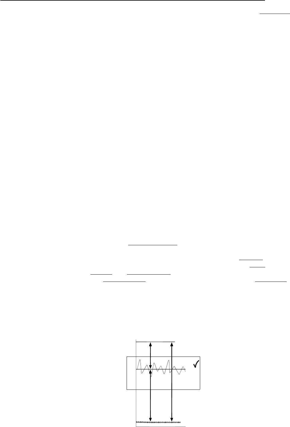
Terminology
The normal operating level is the optimum signal level for best console perfor-
mance, indicated by ‘0’ meter readings and resulting in the +4dBu XLR output level. The channels
operate at 0dBu and the mix stages at –2dBu for extended headroom. Headroom is the extra
level available above normal to allow for loud peaks before the signal becomes clipped resulting in
audible distortion. The signal-to-noise ratio (SNR) is the difference measured in dB between nor-
mal level and residual noise floor (hiss) produced by the console electronics. The dynamic range is
the sum of headroom and SNR representing the maximum signal range possible from quietest to
loudest.
Final word
… A little care with setting gain structure throughout the signal chain will give you
the best performance and most manageable control of the mix.
+1
+3
+6
-12
-16
-9
-6
-3
-1
-20
0
+9
-30
-40
-50
-60
-70
-80
-90
+12
+16
+20
SIGNAL-TO-NOISE RATIO
DYNAMIC RANGE
HEADROOM
CLIPPING
NOISE
NORMAL OPERATING RANGE
SIGNAL
!