
Operation Manual
16 ML5000 User Guide
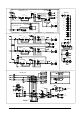
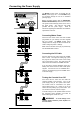
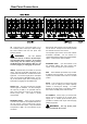
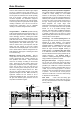
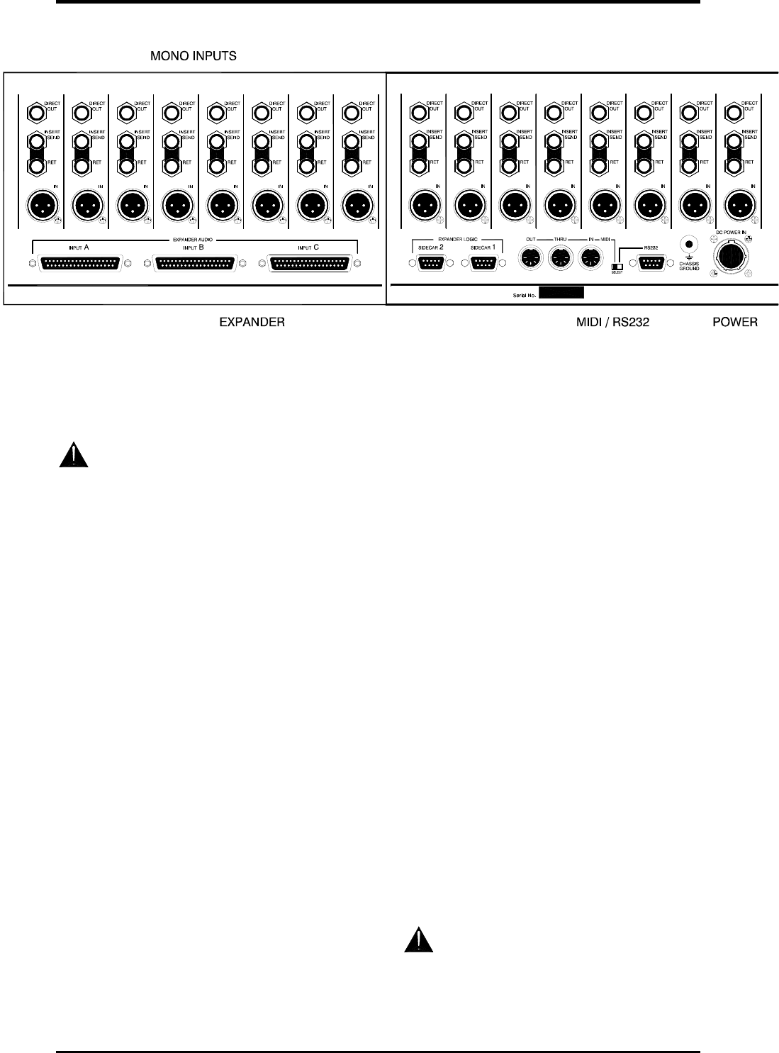
Rear Panel Connections
IN. XLR input for mic or line level signals. Pin 2
hot. Phantom power is fed to pins 2 and 3 through
6k8 series resistors when the front panel +48V
switch is pressed.
WARNING: Do not connect
unbalanced sources or cables to the XLR inputs
when phantom power is selected. To avoid loud
clicks always turn the channel off by pressing
the MUTE switch when switching +48V on or off
and when plugging or unplugging microphones.
INSERT. Separate TRS jack sockets for send and
return. The insert is post-HPF and pre-EQ. It can
operate with both balanced or unbalanced line level
equipment. The channel signal path is interrupted
when you plug into the RETURN socket. You can
tap off the pre-EQ signal without interrupting the
signal path by plugging into the SEND socket.
DIRECT OUT. TRS jack providing the post-fade
channel signal as standard. You can reconfigure
the output as pre-fader or as post-fader with the
AUX 1 send control as a level trim by repositioning
internal jumper links. The output is ground
compensated.
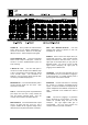
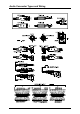
EXPANDER AUDIO. Three 37-pin D-connectors
to connect the outputs of the expander sidecar into
the main console. These provide inputs to all the
mix busses and P/AFL system. They are balanced
and operate at –2dBu. Up to two sidecars may be
connected.
Note that the audio outputs of the first sidecar plugs
into the second. The output of the second presents
the combined mix to the main console.
The expander inputs conform to the Allen & Heath
SYS-LINK II standard. You can connect to a
console fitted with SYS-LINK I using special adapter
cables. Contact Allen & Heath for details.
EXPANDER LOGIC. 9-pin D-connectors to link
the expander sidecar and main console logic
system. Up to two sidecars may be connected.
MIDI. Three standard opto-isolated 5-pin sockets
for MIDI IN, OUT and THRU. For normal console
operation the small slide switch must be in the MIDI
position.
RS232. 9-pin D-connector to connect to the serial
port of a PC for loading new console operating
software or archiving the settings. To enable
RS232 set the slide switch to the RS232 position.
Set it back to the MIDI position when finished.
DC POWER IN. A heavy duty 7-pin connector with
locking ring for connecting to the console power
supply unit. A chassis ground terminal post is
provided for situations that require earth strapping
between equipment.
WARNING: Use only the DC power
cable provided with the console.