
User guide
26 PA-CP User Guide
The AMPLIFIERS
Overview
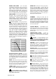
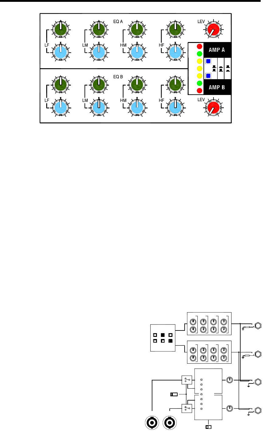
The two built-in power amplifiers are
called Amp A and Amp B. You decide how you
want to use them. Different combinations of the LR,
FB1 and FB2 mixes can be selected according to
your preferred system setup. Each channel includes
a 4-band semi-parametric equaliser for precise
speaker/room frequency shaping. The level controls
let you match the console signals to the speaker
volume you require. A row of LED indicators display
important information about the amplifier status.
The philosophy Our objective was to
produce a powerful, good sounding amplifier in a
compact package for the high end audio
application. The result is a third generation design
benefiting from many refinements and lessons
learned, and adding a few unique touches of our
own. There are none of the common frequency
boosting tricks to try to sweeten the sound from low
quality speakers. Instead we chose to provide a
perfectly flat, accurate response with genuine
performance figures.
The design uses a bipolar assisted MOSFET
Class AB configuration producing a total of 1kW
continuous music power into 4 or 8 ohms. A heavy
duty linear power supply ensures rock solid bass
and full range clarity. The amplifier is fully protected.
Short circuit protection is provided with precision
sharp knee current limit. A built-in program
dependent clip limiter monitors the output easing
psu stress and preventing harmful overload.
Temperature is controlled using a 3 speed twin fan
thermal management system with cut out on
overload. The fans run slow on power up, medium
speed when 35 degrees C is reached, fast speed at
50 degrees, and thermal cut triggers at 85 degrees.
The speakers are protected using relays which
activate if a fault is sensed and have a two second
switch-on delay and instant power off.
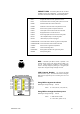
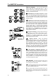
Constant power Most amplifiers produce
their maximum output into 4 ohms with considerably
less into 8 ohms. The unique PA Series CP system
achieves its full rated 500W+500W into either
impedance. This is done using a rear panel slide
switch which sets the power supply for maximum
current (4 ohms) or maximum voltage (8 ohms).
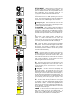
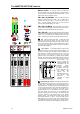
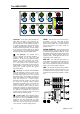
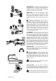
LEVEL Sets the input level to each channel of
the amplifier. Turn the control fully off when
plugging up the equipment. For normal operation
turn it up to the position where it produces loudest
volume required when the console meters are
reading around ‘0’.
SIGNAL METERS Each channel provides
two meter indicators. The green SIG indicator turns
on when audio signal presence is detected. The red
LIM indicator turns on when the built-in limiter starts
to work and the amplifier is producing close to its
maximum output. If LIM lights then back off the
amplifier LEV control until it turns off.
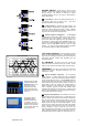
SPK OFF The yellow SPK OFF indicator on
each amplifier channel lights when the speaker relay
is turned off. This happens during the power up
delay, when the amplifier has been put into standby
mode, or when a fault condition is detected.
TMP The TMP indicator lights when the amplifier
operating temperature reaches 50 degrees C and
the cooling fans are running at fast speed. It is quite
normal for this to light when the amplifier is working
hard.
FB1
FB2
MAX
FB1L
L R+R
SIG
TMP
SPK
OFF
OFF
SPK
LIM
MIN
2k5
7k2k5
5k
-10
1k5
7k
+10
10k
2k5
+10
20k
10k
MAX
LIM
SIG
MIN
1k5
-10
2k5
10k
+10
5k
20k
+10
1k 1k200
500
-10
500Hz120Hz
-10
500
2k
+10
70
10030
+10
70
200
-10
20Hz
1k
500Hz
-10
1k
120Hz
-10
200
2k
+10+10
200
100
20Hz
-10
30
FB2R+L R
FB1LFB1
SOURCE SELECT
LM HM HFLF
LM HM HF
4 BAND EQUALISER
LF
A
B
A
B
LEV
LEV
TEMP
PROTECT
SIGNAL
LIMITER
PROTECT
SIGNAL
LIMITER
STANDBY
SPK A SPK B
AMP A
AMP B
RELAY
SLAVE OUT
AMP IN
8 OHM4 OHM