USER GUIDE Publication AP7506
Limited One Year Warranty This product is warranted to be free from defects in materials or workmanship for period of one year from the date of purchase by the original owner. To ensure a high level of performance and reliability for which this equipment has been designed and manufactured, read this User Guide before operating.
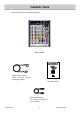
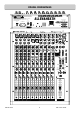
PACKED ITEMS Check that you have received the following: ST2 MIC MIC MIC MIC TEL IN TEL IN LINE LINE LINE LINE CLF OUT CLF OUT ST4 REC OUT CRM SPEAKERS L L L L R R R R L/M L/M L/M L/M MIX B OUT INSERT L L L R MAIN PGM OUT INSERT R EXT MON IN R L AUX M2 M3 M4 INSERT INSERT INSERT ST1 TELCO 1 M1 0 20 10 GAIN M2 10 30 0 MIC LINE 40 50 -10 -6 63 26 0 20 10 GAIN 10 30 0 MIC LINE 40 50 -10 -6 63 26 100Hz HF M3 0 20 10 GAIN M4 10 30 0 MIC LINE 40
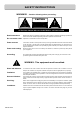
SAFETY INSTRUCTIONS WARNINGS - Read the following before proceeding : CAUTION ATTENTION: RISQUE DE CHOC ELECTRIQUE – NE PAS OUVRIR Read instructions: Retain these safety and operating instructions for future reference. Adhere to all warnings printed here and on the console. Follow the operating instructions printed in this User Guide. Do not remove cover: Operate the console with its covers correctly fitted.
SAFETY INSTRUCTIONS Important Mains plug wiring instructions The console is supplied with a moulded mains plug fitted to the AC mains power lead. Follow the instructions below if the mains plug has to be replaced.
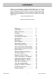
CONTENTS Thank you for purchasing your Allen & Heath XB-14 mixer. To ensure that you get the maximum benefit from the unit please spare a few minutes familiarizing yourself with the controls and setup procedures outlined in this user guide. For further information please refer to the additional information available on our web site, or contact our technical support team. http://www.allen-heath.com http://www.allen-heath.com/xb Warranty .............................................. Packed Items............
PANEL DRAWINGS This device complies with Part 15 of the FCC Rules. Operation is subject to the following two conditions: CAUTION (1) this device may not cause harmful interference, and (2) this device must accept any interference received, including interference that may cause undesired operation. RISK OF ELECTRIC SHOCK DO NOT OPEN ALLEN&HEATH AVIS: RISQUE DE CHOC ELECTRIQUE - NE PAS OUVRIR. CAUTION: FOR CONTINUED PROTECTION AGAINST RISK OF FIRE REPLACE FUSE WITH SAME TYPE AND RATING.
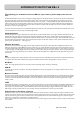
INTRODUCTION TO THE XB-14 The following is a technical overview of XB-14, if you want to, please skip to the next section. The Allen & Heath XB-14 mixer has been carefully and lovingly designed in the beautiful county of Cornwall in the UK and is manufactured alongside a wide range of professional audio mixing consoles.
SPECIFICATIONS (to be completed) Operating Levels Input Mono channel Mic input (XLR) +6 to –63dBu for nominal (+17dBu in max) Mono channel Line input (TRS Jack socket) +10 to –26dBu (+30dBu maximum) Insert point (TRS Jack socket) 0dBu nominal +21dBu maximum Stereo input (TRS Jack sockets) 0dBu nominal (control = Off to +10dB) Stereo input (RCA phono sockets) 0dBu nominal (control = Off to +10dB) Telco channel input (XLR) +10 to –26dBu (+30dBu maximum) External monitor inputs (RCA phono sockets)
SPECIFICATIONS (continued) Headroom Analogue Headroom from nominal (0Vu) Outputs 21dB Analogue Headroom from nominal (0Vu) Mix point 24dB USB in & out headroom from nominal (0Vu) 14dB Crosstalk & Attenuation (dB 22-22kHz) Mono fader attenuation (dB relative to +10dBu) 1kHz/10kHz -100/-90 Mono ON switch attenuation (dB relative to +10dBu) 1kHz/10kHz -100/-90 TELCO fader attenuation (dB relative to +10dBu) 1kHz/10kHz -99/-92 TELCO ON switch attenuation (dB relative to +10dBu) 1kHz/10kHz -100/-100
Dimensions MIC MIC MIC TEL IN MIC CLF OUT LINE LINE LINE LINE M1 M2 M3 M4 INSERT INSERT INSERT INSERT ST2 TEL IN ST4 REC OUT CRM SPEAKERS MIX B OUT INSERT L L L L L L R R R R R CLF OUT L/M L/M L/M L/M L MAIN PGM OUT INSERT R EXT MON IN R L AUX TELCO 1 M1 0 20 10 GAIN M2 10 30 0 MIC LINE 40 50 -10 -6 63 26 0 20 10 GAIN 10 30 0 MIC LINE 40 50 -10 -6 63 26 100Hz HF 0 20 10 M4 10 30 0 MIC LINE 40 50 -10 -6 63 26 100Hz HF 12kHz M3 GAIN T1
BLOCK DIAGRAM R L PP + - HPF + - GAIN GAIN LF MONO CHANNEL HPF INSERT HF HF 3 BAND EQUALISER HM LOW=FADER UP ON PEAK SIGNAL PFL MUTE REMOTE MUTE METER ON PFL DISABLE ON SWITCH LOGIC PEAK SIGNAL ON DISABLE ON PFL OPTIONAL OPERATION STANDARD OPERATION MIX B PAN AUX MIX B PAN AUX AUX MIX B PAN 1 2 3 4 ON ON ON ON T1 T2 1 2 ON ON ON ON 3 4 MONO PGM AUX MIC CHANNELS 1 - 4 PREFADE PFL ACTIVE XB-14 BLOCK DIAGRAM FADER PRE FADER PRE FADER PRE DISABLE STEREO MUTE C
MONO INPUT CHANNEL MIC 1 Mic Input Socket 2 Line Input Jack Socket 3 Insert Jack Socket 4 Gain Control Standard 3-Pin XLR socket wired as Pin 1=Chassis, Pin 2=hot (+), Pin 3=Cold (-). 1 LINE Standard 1/4” (6.25mm) Jack socket for balanced or unbalanced line level signals. Wired Tip=Hot (+), Ring=cold (-), Sleeve=Chassis. The Line input overrides the Mic input, so if you want to hear something plugged in to the xlr socket, make sure nothing is plugged into the Line input.
MONO INPUT CHANNEL M1 0 20 10 GAIN 6 10 30 0 MIC LINE 40 HF EQ The HF (High Frequency) equaliser affects the frequency response of the higher audible frequencies. The corner frequency of 12kHz is around 3dB from the maximum cut or boost of the circuit. It has plenty of gain and actually gives slightly more that the +/-15dB legend suggests. 50 -10 -6 63 26 dBr 20.00 15.00 100Hz 10.00 5.00 HF 6 0.00 12kHz -5.00 -10.00 -15.00 -15 500 +15 650 -20.00 10.
MONO INPUT CHANNEL 9 PRE AUX 9 +6 OO MIX B BUS 10 11 L 12 14 MIX B 11 PAN 12 ON Switch 13 SIGNAL & PEAK LEDs 14 PFL Switch 15 Fader The MIX B switch routes the channel signal to a stereo bus which is independent of the main PGM (program) bus. The signal is post-fade and follows the PAN control. The MIX B bus can be used for creating mixes for recording or clean-feed sources for external equipment. R REM MUTE 13 This control sends a signal to an auxiliary bus.
TELCO CHANNELS 1&2 TEL IN 1 TEL IN 2 CLF OUT 3 TELCO Input Gain 4 100Hz High Pass filter 5 TELCO Channel EQ The Telephone Communication channel input XLR socket. Wired as Pin 1=Chassis, Pin 2=hot (+), Pin 3=Cold (-). 1 Standard XLR output connector for the Clean-Feed output from the Telephone Communication channel. Wired Pin 1=Chassis, Pin 2=hot (+), Pin 3=Cold (impedance balanced ground). CLF OUT 2 TELCO 1 T1 0 GAIN 5 10 The Telephone Communication channel input gain control.
TELCO CHANNELS 1&2 6 TALK 6 TALK 7 CLF SCE CLF SCE PGM 7 AUX The TALK switch enables the presenter or operator to communicate with the telephone caller with the presenters channel fader down so the presenters voice does not go to the program mix. The source for the TALK signal is one of the mono channels, pre-selected by links set within the XB-14, the factory default is mono channel 1. The signal source is pre-fade and pre-mute on the selected mono channel.
TELCO CHANNELS 1&2 11 = PAN L R 11 12 13 ON Switch This mechanically latching switch operates the TELCO channel mute circuitry, turning the signal to the PGM, MIX B and Aux buses on or off. The switch is illuminated green when pressed. There is an option to disable the switch (make permanently ON) using the option switches on the rear-panel. If this is activated, then the switch will be illuminated green regardless of whether it is pressed or not.
STEREO INPUT CHANNELS ST1 & ST2 FOR CLARITY ONLY ST1 CHANNEL IS DESCRIBED HERE ST2 L 2 1 ST1Inputs 2 ST2 Inputs 3 Stereo source selector switch 4 Stereo input level controls 5 Stereo channel EQ Standard 1/4” jack sockets for input signals to ST1 L & R inputs. Wired Tip=Hot(+), Ring=cold (-), Sleeve=Chassis. Fully balanced. Nominal input level = 0dBu. R L/M 1 ST1 R ST2 -10 4 -5 0 -20 Standard RCA phono sockets for ST2 L & R inputs. Unbalanced. Nominal input level = 0dBu.
STEREO INPUT CHANNELS ST1 & ST2 FOR CLARITY ONLY ST1 CHANNEL IS DESCRIBED HERE PRE AUX 7 BAL 8 ON (+START/CUE) switch The balance control adjusts the relative levels of the left & right signals in the stereo input channel as they are sent to the PGM bus and the MIX B bus. Set to the mid position, the signals are balanced equally. With the balance control set fully anticlockwise the right channel will be fully attenuated and the left channel will increase by approximately 3.5dB.
STEREO INPUT CHANNELS ST3 & 4 SIMILAR TO THE ST1 & 2 CHANNELS— THE DIFFERENCES ARE DETAILED HERE. REC OUT L 1 R L/M 1 REC OUT 2 USB RTN (ST6) level 3 CRM SPEAKERS outputs Standard RCA phono sockets for the record output which is sourced from pre the main PGM fader, and just after the main L & R inserts. Nominal level = 0dBu, unbalanced. ST5 R USB ST6 RTN 2 The source for the ST6 input is from the USB audio device, in other words from an external computer.
MASTER SECTION 4 3 MIX B OUT INSERT L L 1 MIX B OUT 2 External Monitor Input 3 Main PGM Inserts 4 Main PGM Outputs 5 AUX Output 6 Mono Output 7 Headphone Output Sockets L R MAIN PGM OUT INSERT R EXT MON IN R L 2 AUX MONO OUT R 5 1 GUEST PHONES 1 6 GUEST PHONES 2 CRM PHONES 7 POWER +16 +9 +6 +3 0VU -3 -6 -9 -12 -16 -20 -30 PHANTOM POWER TO MICS +16 +9 +6 +3 0VU -3 -6 -9 -12 -16 -20 -30 L R PFL ACTIVE GUEST PHONES SELECTION CRM+PHONES SELECTION AUX MIX B USB IN EXT MON A
MASTER SECTION MIX B OUT INSERT L L 8 48v Phantom Power switch 9 Main Left & Right meters L R MAIN PGM OUT INSERT R EXT MON IN R L AUX MONO OUT R GUEST PHONES 2 CRM PHONES POWER 48V 8 +16 +9 +6 +3 0VU -3 -6 -9 -12 -16 -20 -30 PHANTOM POWER TO MICS 10 +16 +9 +6 +3 0VU -3 -6 -9 -12 -16 -20 -30 L 9 R PFL ACTIVE GUEST PHONES SELECTION CRM+PHONES SELECTION AUX MIX B 11 USB IN EXT MON ALLEN& HEATH GUEST PHONES 1 10 13 MIN CUT SPKS GUEST PHONES Source Selector switches 13 CRM Sp
MASTER SECTION MIX B OUT INSERT L L L R MAIN PGM OUT INSERT R 14 CRM Speakers level 15 DIM & Cut CRM Speakers 16 MIC FADER UP =CUT Speakers 17 Control Room Phones level 18 Guest Phones level 19 MIX B level 20 Program Mix Fader EXT MON IN Adjusts the level of the signal to the control room speaker outputs from off (fully attenuated) to unity gain.
REMOTE INTERFACE CONNECTORS 15 Way D socket connector REMOTE A PIN FUNCTION 1 M1 FADER UP LOGIC (OPEN COLLECTOR OUTPUT) 2 M3 FADER UP LOGIC (OPEN COLLECTOR OUTPUT) 3 T1 FADER UP LOGIC (OPEN COLLECTOR OUTPUT) 4 M1 EXTERNAL MUTE (INPUT, ACTIVE LOW) 5 M3 EXTERNAL MUTE (INPUT, ACTIVE LOW) 6 T1 EXTERNAL MUTE (INPUT, ACTIVE LOW) 7 CUT CRM SPEAKERS (INPUT, ACTIVE LOW) 8 GROUND 9 M2 FADER UP LOGIC (OPEN COLLECTOR OUTPUT) 10 M4 FADER UP LOGIC (OPEN COLLECTOR OUTPUT) 11 T2 FADER UP LOGIC (OPEN
REMOTE INTERFACE CONNECTORS 9 Way D socket connector EXTERNAL METER PIN FUNCTION 1 +15V POWER 2 -15V POWER 3 GROUND 4 LEFT METER 5 RIGHT METER 6 GROUND 7 GROUND 8 GROUND 9 +10V POWER External Meter socket This can be used to feed the main Program PGM L & R signals to external metering equipment. These are line level analogue signals, the level at 0VU will be 0dBu. +/- 15V power is also available to power meter circuits, current draw should be kept under 100mA or so.
REMOTE INTERFACE CONNECTORS REMOTE A Connector wiring The REMOTE A connector is used for the “Fader Up” logic signals from the Mono and Telco channel faders. It is also used for remote muting of channels and control room speakers.
USB CONNECTION ST4 REC OUT L CRM SPEAKERS L MIX B OUT L R R R L/M L/M L/M INSERT L L R L MAIN PGM OUT INSERT R EXT MON IN R L AUX ST3 ST5 R USB SEND 5 -30 10 10 OO RETURN ST6 (USB) 3/4 5/USB ST5 -10 0 ST7 -10 -5 0 OO 0 HF 5 -30 10 OO 10 HF 12kHz +15 +16 +9 +6 +3 0VU -3 -6 -9 -12 -16 -20 -30 PHANTOM POWER TO MICS -5 IN -20 5 -30 10 48V MIX B PGM MIX -20 5 POWER AUX+MONO USB SOURCE SELECT ST5 5 GUEST PHONES 2 CRM PHONES -5 -10 -20 5 0 MONO OUT R 12
APPLICATION DIAGRAM: SELF OPERATION Guests Operator Telephone caller Telephone Hybrid Module CD CD Jingle Limit Single room Self Operation System Compressor/Limiter Amp Control Room Monitor Speakers Music sources Sound sources Notes: Ensure FADER UP = CUT SPKS switch is enabled to avoid feedback from CRMs The Telephone module could be substituted with a Skype system.
APPLICATION DIAGRAM: STUDIO+CONTROL ROOM Telephone caller Telephone caller Studio Guest Presenter KEY Microphone signals to mono inputs Telephone line in (or exchange) Line level to/from telephone module Line level stereo signals Telephone call handling Headphone signals PGM inserts to limiter Program mix for transmission Telephone Hybrid Module USB lead Control Room Control Room Monitor Speakers Amp CD Music sources CD Sound sources Jingle Limit MIC MIC LINE MIC L INE T EL IN MIC LINE
APPLICATION TIPS: OFF-AIR CALL RECORDING This diagram shows the basic mixer setup using the Aux bus to record an interview with a telephone caller off-air, whilst playing music through stereo channel ST1. The interview could be recorded from the Aux out or via the USB port as shown here.
APPLICATION TIPS: PLAYBACK OF RECORDED CALL Following the previous page... This diagram shows the recorded interview with the telephone caller being played out on-air from the computer via USB.
FIXING TO A RACK OR FURNITURE The XB-14 can be fitted to a 19” rack or incorporated into studio furniture using the optional 19” rack fixing kit. The following pictures give you an idea of how the rack fixing kit is fitted to the XB-14. Should you decide to purchase the kit, please follow the fitting instructions provided with the kit.
WIRING NOTES PROCESSOR Insert cable wiring RETURN S INSERT T OUT T R S R SEND GROUND RETURN SEND S T R IN LINK RING TO SLEEVE TO UNBALANCE Y-Adapter Y-Adapter 2 Outputs to 1 Input RCA PHONO CABLE RCA phono jacks adapter 1 Output to 2 Inputs UNBALANCED No ! UNBALANCED INSTRUMENT CABLE UNBALANCED BALANCED TRS JACK CABLE BALANCED Sleeve=ground Sleeve=ground Ring=cold (-) Ring=cold (-) Tip=hot (+) TO INPUT Tip=hot (+) 2=hot (+) 1=ground BALANCED MIC CABLE BALANCED 1=ground
PRODUCT SUPPORT Investigate ALLEN & HEATH’s other ranges at www.allen-heath.com Large Live Sound mixers — iLive digital, ML and GL Series Small Format Live Sound mixers — ZED, MixWizards , PA Series, XB DJ products — Xone Series Sound Management Series — iDR Series Registering your product Thank you for buying the Allen & Heath XB-14 mixer. We hope that you are happy with it and that you or your end users enjoy many years of faithful service with it. Please go to www.allen-heath.com/register.
NOTES
NOTES