ZED-10 USER GUIDE Publication AP7880
CONTENTS Warranty....................................................................... 4 Conformity Statement................................................ 5 Safety Instructions ....................................................... 6 Packed Items Checklist .............................................. 9 Introduction to ZED-10............................................. 10 Specifications ................................................................ 12 Dimensions ......................
WARRANTY Limited One Year Warranty This product is warranted to be free from defects in materials or workmanship for period of one year from the date of purchase by the original owner. To ensure a high level of performance and reliability for which this equipment has been designed and manufactured, read this User Guide before operating.
EMC & SAFETY This product complies with the European Electro magnetic Compatibility directives 89/336/EEC & 92/31/EEC and the European Low Voltage Directives 73/23/EEC & 93/68/EEC. This product has been tested to EN55103 Parts 1 & 2 1996 for use in Environments E1, E2, E3, and E4 to demonstrate compliance with the protection requirements in the European EMC directive 89/336/ EEC. During some tests the specified performance figures of the product were affected.
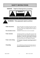
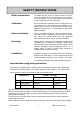
SAFETY INSTRUCTIONS WARNING - Read the following before proceeding : CAUTION ATTENTION: RISQUE DE CHOC ELECTRIQUE – NE PAS OUVRIR ! WARNING: This equipment must be earthed. Read instructions: Retain these safety and operating instructions for future reference. Adhere to all warnings printed here and on the console. Follow the operating instructions printed in this User Guide. Do not remove cover: Operate the console with its covers correctly fitted.
SAFETY INSTRUCTIONS Water and moisture: To reduce the risk of fire or electric shock do not expose the console to rain or moisture or use it in damp or wet conditions. Do not place containers of liquids on it which might spill into any openings. Ventilation: Do not obstruct the ventilation slots or position the console where the air flow required for ventilation is impeded. If the console is to be operated in a rack unit or flightcase ensure that it is constructed to allow adequate ventilation.
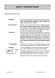
SAFETY INSTRUCTIONS General Precautions: Damage : Environment : Cleaning : Transporting : Hearing : 82 Allen & Heath To prevent damage to the controls and cosmetics avoid placing heavy objects on the control surface, scratching the surface with sharp objects, or rough handling and vibration. Protect from excessive dirt, dust, heat and vibration when operating and storing. Avoid tobacco ash, smoke, drinks spillage, and exposure to rain and moisture.
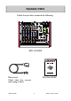
PACKED ITEMS Check that you have received the following: Mic Mic Mic Mic Line Line GTR 1 GTR 2 Hi Z O/P Level Switch Left Left Left Right Right Right Hi Z USB Left Left Left Right Right Right USB IN L 20 0 40 20 0 40 GAIN - 10 10 60 40 M L 20 0 40 GAIN - 10 10 HPF 60 40 M L 20 USB IN R 40 GAIN - 10 10 HPF 60 40 M G - 10 10 HPF HF HF HPF 0 HF 500 -15 650 +15 500 1k -15 650 +15 500 1k 200 2k 4k 2k 500 1k 120 4k 2k Aux-FX 120 4k 2k 3k
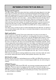
INTRODUCTION TO THE ZED-10 Background Overview: The Allen & Heath ZED series mixers have been carefully and lovingly designed in the beautiful county of Cornwall in the UK and are manufactured alongside a wide range of professional audio mixing consoles to the same high standards.
INTRODUCTION TO THE ZED-10 EQ: The ZED-10 and ZED-10FX mixers are equipped with a 3-band equaliser circuit on each mono input, with swept mid frequency section, and a 2-band EQ on the stereo channels. The frequency and response of each has been carefully chosen to give the maximum performance when using the EQ on a variety of sources. Record Bus: A separately switched stereo bus can be routed to from any channel creating a selective recording bus, monitoring bus or stereo clean feed output.
SPECIFICATIONS Operating Levels Input Mono channel (XLR) Input -10 to –60dBu for nominal (+11dBu in max) Mono channel Line Input (Jack socket) +10 to –40dBu (+31dBu maximum) Stereo Input (Jack or phono sockets) 0dBu nominal (control = Off to +15dB) Output L/R Outputs ( XLR) Normal/DI out 0dBu/-30dBu +21dBu/-9dBu maximum. Aux & FX Outputs (Jack sockets) 0dBu nominal. +21dBu maximum. Record & Monitor Outputs (phono sockets) 0dBu nominal. +21dBu maximum.
DIMENSIONS Mic Mic Line Mic Line Mic GTR 1 O/P Level Switch Left Left Left Right Right Right GTR 2 Hi Z Hi Z Left Left USB Left USB IN L 20 0 40 GAIN 20 0 40 GAIN 60 40 M L - 10 10 20 0 40 GAIN 60 40 M L - 10 10 HPF 20 USB IN R 40 GAIN 60 40 M G - 10 10 HPF Right Right HPF 0 0 HF HF HF HF 500 650 -15 +15 1k 500 650 f 500 2k 120 4k 650 f 500 2k 120 4k 650 +15 -15 f 2k f 2k 3k MID LF +15 120 -15 4k 3k MID LF +15 120 -15 LF
BLOCK DIAGRAM SCHEMATIC MIC IN LINE IN L R USB AUDIO INPUT INSTRUMENT IN ST1-b L R L R ST1-a L USB AUDIO INPUT L R Phantom Power GAIN + - 100Hz HM HF HF 3 BAND EQUALISER MONO CHANNEL HPF LF STEREO CHANNEL MONO CHANNELS 3&4 MONO CHANNELS 1&2 CLASS A FET HI-Z DI GAIN BOOST GAIN LF 2 BAND EQUALISER STEREO CHANNEL 1 PLAYBACK STEREO CHANNEL 2 PLAYBACK INPUT PLAYBACK LEVEL LEVEL PFL PFL BAL RECORD PAN FX AUX RECORD FX AUX PLAYBACK TO AUX LEFT INSERT RIGHT INSERT AUX MIX
MONO INPUT CHANNEL 1 & 2 Mic Input Socket Standard 3-Pin XLR socket wired as Pin 1=Chassis, Pin 2=hot (+), Pin 3=Cold (-). Line Input Jack Socket Standard 1/4” (6.25mm) Jack socket for balanced or unbalanced line level signals. Wired Tip=Hot(+), Ring=cold (-), Sleeve=Chassis. The Line input connects to the XLR input through a circuit, so be aware that the two signals will add together if both inputs are plugged in simultaneously.
MONO INPUT CHANNEL 1 & 2 HF EQ The HF (High Frequency) equaliser affects the frequency response of the higher audible frequencies. The corner frequency of 12kHz is around 3dB from the maximum cut or boost of the circuit. It has plenty of gain and actually gives slightly more that the +/-15dB legend suggests. HF -15 500 650 +15 1k 200 f 2k 3k MID 120 dBr 20.00 4k 15.00 10.00 5.00 0.00 -5.00 -15 +15 -10.00 LF -15.00 -20.00 10.00 Hz -15 1000.00 10000.00 30000.
MONO INPUT CHANNEL 1 & 2 HF -15 500 FX send This controls the level of signal that is sent to the effects bus and FX output from the channel. The signal is postlevel which means it is affected by the channel Level control (so it stays in proportion to the signal going to Mix) and the send control has 6dB gain fully clockwise. There is no master level control for the FX bus.
MONO INPUT CHANNEL 3 & 4 Hi Z input The only difference between mono inputs 1-2 and 3-4 is the Hi Z inputs for guitars or other instruments. Standard 1/4” (6.25mm) Jack socket for unbalanced line level signals or instrument pickups. Wired Tip=Hot(+), Ring=cold (-), Sleeve=Chassis. The Hi Z input connects to the XLR input through a circuit, so be aware that the two signals will add together if both inputs are plugged in simultaneously.
STEREO INPUT CHANNEL 1 ST-1b Inputs Standard RCA Phono sockets for unbalanced line level stereo signal sources from equipment such as CD players, sound modules or MP3 players. If your MP3 player has a mini jack socket (most common) use a stereo mini jack plug to 2 x RCA Phono lead. Left Right ST-1a Inputs Standard 1/4” jack sockets for line level stereo signals.
STEREO INPUT CHANNEL 1 FX send This controls the level of signal that is sent to the effects bus and FX output from the stereo channel. The signal is post-level which means it is affected by the channel Level control (so it stays in proportion to the signal going to Mix) and the send control has 6dB gain fully clockwise. There is no master level control for the FX bus. HF -15 +15 -15 +15 LF FX 0 +6 AUX send Controls the level of signal sent to the Auxiliary output from the stereo channel.
STEREO INPUT CHANNEL 2 ST-2 Input The USB audio input is connected through the break contacts of the standard 1/4” (6.25mm) jack sockets. Plugging into the jacks will override the USB input, so if you want to use the ST-2 channel for the USB input signal, make sure nothing is plugged into the jack sockets.
MASTER SECTION O/P Level Switch Main Mix Insert jack sockets Standard 1/4” (6.25mm) jack sockets wired: Tip = send, Ring = return, Sleeve = Chassis. Nominal level is 0dBu. Effects & Aux bus Outputs Standard 1/4” (6.25mm) jack sockets wired: Tip = hot, Ring = cold, Sleeve = Chassis. Nominal level is 0dBu. The FX out is the Effects bus output, and can be used for connecting to external equipment such as an effects processor. The AUX out is taken from after the AUX MIX master level control.
MASTER SECTION Stereo Meters 12 Segment LED meters with fast attack (4mS) and medium decay (1S). The meters display the signals selected by the Phones Select switches, or the mono Listen signal (PFL) if activated by any of the Listen switches. +16 +9 +6 +3 0 -3 -6 -9 -12 -16 -20 -30 0 LEVEL PFL (Pre-Fade Listen) active LED A red LED to indicate a Listen switch has been pressed on one of the channels.
CONNECTING TO A COMPUTER USB lead type A to B Left Mic Mic Mic Mic Line Line GTR 1 GTR 2 Hi Z O/P Level Switch Left Left Right Right Right Hi Z Left USB Left Left Right Right USB IN L 20 0 40 20 0 40 GAIN 60 40 M L - 10 10 20 0 40 GAIN 60 40 M L - 10 10 HPF 20 USB IN R 40 GAIN 60 40 M G - 10 10 HPF Right HF HF 0 HF -15 500 650 -15 +15 1k 500 200 650 -15 +15 1k 500 200 f 2k 4k 650 2k 120 4k 500 2k 650 Aux-FX +15 1k f LF LF -15 +15
APPLICATION DRAWING—LIVE MIXING Allen & Heath 25 ZED-10 User Guide
APPLICATION DRAWING—STUDIO RECORDING Allen & Heath 26 ZED-10 User Guide
APPLICATION DRAWING—USING USB FOR EFFECTS LOOP-1 A simple way to use effects processor plugins running on a computer audio application or DAW is to use the USB audio connection and select the Aux-FX as the output source. In the audio application route the FX signal (USB Right) to a track or bus containing the effects plugin and route the track/bus output back to the ZED (USB audio device).
APPLICATION DRAWING—USING USB FOR EFFECTS LOOP-2 USB FX loop Using ST2 for Effects Return In the audio software application add the plugin to the track (here it’s a reverb) Try to ensure the processor output is effect only (no dry signal). In the audio software create route the right USB channel to an audio track (from FX). Then route the track output to the USB audio device in stereo (back to the ZED).
WIRING INFORMATION PROCESSOR Insert cable wiring RETURN S INSERT T OUT T R S R SEND GROUND RETURN SEND S T R IN LINK RING TO SLEEVE TO UNBALANCE General Wiring Information Y-Adapter Y-Adapter 2 Outputs to 1 Input RCA PHONO CABLE RCA phono jacks adapter 1 Output to 2 Inputs UNBALANCED No ! UNBALANCED INSTRUMENT CABLE UNBALANCED BALANCED TRS JACK CABLE BALANCED Sleeve=ground Sleeve=ground Ring=cold (-) Ring=cold (-) Tip=hot (+) Tip=hot (+) TO INPUT Yes 2=hot (+) 1=ground B
See more products from ALLEN & HEATH at: www.allen-heath.com Large Live Sound mixers — iLive digital, ML and GL Series Small Format Live Sound mixers — ZED, MixWizards and PA Series DJ products — Xone Series Sound Management Series — iDR Series Registering your product Thank you for buying the Allen & Heath ZED-10 mixer. We hope that you are happy with it and that you enjoy many years of faithful service with it. Please go to www.allen-heath.com/register.