ZED SIXTY-10FX & ZED SIXTY-14FX USER GUIDE Publication AP8765
CONTENTS Warranty ......................................................................... 4 Conformity Statement ................................................. 5 Safety Instructions ......................................................... 6 Packed Items Checklist ................................................ 9 Introduction to ZED Sixty-10FX & 14FX ............... 10 Specifications .................................................................. 12 Dimensions .........................
WARRANTY Limited One Year Warranty This product is warranted to be free from defects in materials or workmanship for period of one year from the date of purchase by the original owner. To ensure a high level of performance and reliability for which this equipment has been designed and manufactured, read this User Guide before operating.
EMC & SAFETY This product complies with the European Electro magnetic Compatibility directives 2004/108/EC and the European Low Voltage Directives 2006/95/EC. This product has been tested to EN55103 Parts 1 & 2 2009 for use in Environments E1, E2, E3, and E4 to demonstrate compliance with the protection requirements in the European EMC directive 2004/108/EC. During some tests the specified performance figures of the product were affected.
SAFETY INSTRUCTIONS WARNING - Read the following before proceeding : CAUTION AC MAINS IN ~ ATTENTION: RISQUE DE CHOC ELECTRIQUE – NE PAS OUVRIR ! FUSE TYPE T 3.15A 20mm T 5.0A 20mm AC SUPPLY 220 - 240V~ 100 - 120V~ 47-63Hz 320VA MAX 300W MAX WARNING: This equipment must be earthed. SERIAL No: Made in the UK by ALLEN & HEATH WARNING - THIS APPARATUS MUST BE EARTHED. Read instructions: Retain these safety and operating instructions for future reference.
SAFETY INSTRUCTIONS Water and moisture: To reduce the risk of fire or electric shock do not expose the console to rain or moisture or use it in damp or wet conditions. Do not place containers of liquids on it which might spill into any openings. Ventilation: Do not obstruct the ventilation slots or position the console where the air flow required for ventilation is impeded. If the console is to be operated in a rack unit or flightcase ensure that it is constructed to allow adequate ventilation.
SAFETY INSTRUCTIONS General Precautions: Damage : To prevent damage to the controls and cosmetics avoid placing heavy objects on the control surface, scratching the surface with sharp objects, or rough handling and vibration. Environment : Protect from excessive dirt, dust, heat and vibration when operating and storing. Avoid tobacco ash, smoke, drinks spillage, and exposure to rain and moisture. If the console becomes wet, switch off and remove mains power immediately.
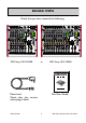
PACKED ITEMS Check that you have received the following: Mic Mic Mic Line GTR 1 GTR 2 Hi Z Left O/P Level Switch Left Left Right Right Right Mic Mic Mic Mic Mic Mic Mic Mic Line Line Line Line Line Line GTR 1 GTR 2 Left Left Right Right Left 20 0 40 GAIN 20 0 40 GAIN - 10 10 60 40 M L 20 60 40 M G USB IN L HF 0 HF 5 500 650 -15 +15 1k 500 200 650 500 200 f 2k 120 4k 650 2k 120 4k 500 650 +15 1k 2k f 2k 3k MID +15 120 4k 3k MID
INTRODUCTION TO THE ZED Sixty Background Overview: The Allen & Heath ZED series mixers have been carefully and lovingly designed in the beautiful county of Cornwall in the UK and are manufactured alongside a wide range of professional audio mixing consoles to the same high standards.
INTRODUCTION TO THE ZED Sixty EQ: The ZED Sixty mixers are equipped with a 3-band equaliser circuit on each mono input, with swept mid frequency section, and a 2-band EQ on the stereo channels. The frequency and response of each has been carefully chosen to give the maximum performance when using the EQ on a variety of sources. Record Bus: A separately switched stereo bus can be routed to from any channel creating a selective recording bus, monitoring bus or stereo clean feed output.
SPECIFICATIONS Operating Levels Input Mono channel (XLR) Input -10 to –60dBu for nominal (+11dBu in max) Mono channel Line Input (Jack socket) +10 to –40dBu (+31dBu maximum) Stereo Input (Jack or phono sockets) 0dBu nominal (control = Off to +15dB) Output L/R Outputs ( XLR) Normal/DI out 0dBu/-30dBu +21dBu/-9dBu maximum. Aux & FX Outputs (Jack sockets) 0dBu nominal. +21dBu maximum. Record & Monitor Outputs (phono sockets) 0dBu nominal. +21dBu maximum.
DIMENSIONS ZED Sixty-10FX Mic Mic Mic Line GTR 1 GTR 2 Hi Z O/P Level Switch Left Left Left Right Right Right Mic Mic Mic Mic Mic Mic Mic Mic Line Line Line Line Line Line GTR 1 GTR 2 Hi Z Left Left Right Right USB Left Left Left Right Right Right 0 40 20 0 40 GAIN 60 40 M L 20 0 40 GAIN - 10 10 60 40 M L Left Left Right Right Right USB IN L HPF 0 20 USB IN R 40 GAIN - 10 10 60 40 M G HPF - 10 10 HPF HF -15 500 650 -15 +15 1k 500
BLOCK DIAGRAM SCHEMATIC MIC IN LINE IN L R USB AUDIO INPUT INSTRUMENT IN ST1-b L R L ST1-a R L R USB AUDIO INPUT L R 48V To Mics GAIN + - HPF LF HM HF 3 BAND EQUALISER MONO CHANNEL 100Hz MUTE MUTE RECORD PAN FX AUX RECORD FX AUX FX TO AUX RECORD EFFECTS TO MIX FADER Listen MONO FADER Listen Listen BAL Default = Pre-Mute STEREO FADER PLAYBACK FADER TAP/PARAMETER SEL DOWN SEL UP BANK EFFECT TYPE MONO CHANNELS 3&4 (10FX) 7&8 (14FX) MONO CHANNELS 1&2 (10FX) 1-6 (14FX) CL
MONO INPUT CHANNEL 1&2 (10FX) 1-6 (14FX) Mic Input Socket Standard 3-Pin XLR socket wired as Pin 1=Chassis, Pin 2=hot (+), Pin 3=Cold (-). Mic Mic Line Line 0 0 20 40 GAIN 20 GAIN - 10 10 - 10 10 60 40 M L HPF HF HF -15 500 650 -15 +15 1k 500 Line Input Jack Socket Standard 1/4” (6.25mm) Jack socket for balanced or unbalanced line level signals. Ring=coldMic (-), Mic Wired Tip=Hot(+), Mic Sleeve=Chassis.
20 20 40 40 20 GAIN GAIN - 10 10 - 10 10 60 40 M L 40 20 GAIN 60 40 M L 40 20 GAIN - 10 10 60 40 M L GAIN - 10 10 60 40 M L - 10 10 MONO INPUT CHANNEL 1&2 (10FX) 1-6 (14FX) HPF HPF HPF HF EQ HF The HF (High Frequency) HF equaliser affects the HFfrequency re- HF -15 500 650 +15 1k 200 f 2k 200 f 15.00 4k MID 120 10.00 200 f 2k dBr 20.00 3k 120 HF sponse of the higher audible frequencies.
-15 -15 +15 +15 -15 LF LF +15 -15 LF +15 -15 LF LF MONO INPUT CHANNEL 1&2 (10FX) 1-6 (14FX) -15 -15 +15 FX 0 FX +6 AUX AUX -15 +15 -15 +15 -15 FX +15 send This controls the level of signal that is sent to the effects FX FX FX bus and 0FX output from the channel. The signal is post-fade 0 0 which means it is affected by the channel fader (so it stays in proportion to the signal going to Mix) and the send con+6 +6 +6 trol has 6dB gain fully clockwise. There is no master FX bus.
MONO INPUT CHANNEL 3&4 (10FX) 7&8 (14FX) Hi Z input The only difference between these mono inputs is the Hi Z Left inputs for guitars or other instruments. Mic Mic GTR 1 GTR 2 Hi Z Hi Z 0 40 20 0 40 GAIN 40 L 20 GAIN - 10 10 HPF Standard 1/4” (6.25mm) Jack socket for unbalanced line level signals or instrument pickups. Wired Tip=Hot(+), Ring=cold (-), Sleeve=Chassis.
STEREO INPUT CHANNEL 1 ST-1b Inputs Standard RCA Phono sockets for unbalanced line level stereo signal sources from equipment such as CD Left players, sound modules or MP3 players. If your MP3 player has a mini jack socket (most common) use a stereo mini jack plug to 2 x RCA Phono lead. Left Right Left Right ST-1a Inputs Standard 1/4” jack sockets for line level stereo signals.
-15 -15 +15 LF +15 Bank 9-16 LF -15 SEL STEREO INPUT CHANNEL 1 -15 +15 +15 +15 0 +15 FX 0 +6 FX send PARAMETER (HOLD) This controls the level of signal that is sent to the effects bus and0FX output from the stereo channel. The signal is TAP post-fade which means it is affected by the channel fader (so it +6stays in proportion to the signal going to Mix) and the send controlFX has to 6dB gain fully clockwise. PLAYBACK TO AUX level control for the FX bus.
5 5 Left Left Left Right STEREO INPUT CHANNEL 2 Right Left Left Right Right 0 Right The rest of the features of the ST-2 channel are as described for ST-1 (level) Plate (decay) 1 Dly+verb 9 Note: Important ! TAP +15 back or stereo input it is best to keep the level (regen) turned (colour) so that unwanted noise from 3 Dly+verbcontrols 11 Plate down Aux-FX the inactive USB device is not passed to the mix.
Right Left Right USB Left ZED-FX EFFECTS PROCESSOR USB IN L USB IN R Right Right TAP 5 +15 +15 1 Dly+verb (level) 9 Plate (decay) 2 Dly+verb (size) 10 Plate (predly) 3 Dly+verb (regen) 11 Plate (colour) 4 PingPong(regen) 12 Hall1 (size) 5 BeatDly (regen) 13 Hall2 (size) 6 Ambient (echo) 14 Arena (size) 7 SlapVerb (size) 15 Flanger (dpth) 8 DoubleZED(size) 16 Chorus (dpth) Effects Type Selection LED. 8 Green LED’s show one of 16 effects types available.
ZED-FX EFFECTS PROCESSOR Effects Type List & Description. There are 16 different effects presets in the ZED Effects Processor. Each is fed with a mono signal from the FX bus, and the output from the effects processor is in stereo. Each preset has a parameter adjust control which is matched to the preset.
MASTER SECTION Main Mix Out XLR connectors Standard XLR output connectors for the Left Left main stereo mix. Impedance balanced to aid interference rejection. A recessed switch on the rear panel reRight Right Mic duces the level by 30dB if it is required to submix GTR 2 these outputs into the XLR inputs of another mixer. Hi Z Left Left Left Main Mix Insert jack sockets Standard 1/4” (6.25mm) jack sockets wired: 0 20 Tip 40= send, Ring = return, Sleeve = Chassis.
MASTER SECTION O/P Level Switch ht Stereo Meters 12 Segment LED meters with fast attack (4mSec) and medium decay (1Sec). The meters display the signals selected by the Phones Select switches, or the mono Listen signal (PFL) if activated by any of the Listen switches. d +16 +9 +6 +3 0 -3 -6 -9 -12 -16 -20 -30 X K 0 LEVEL +10 L Phones Monitor Source PFL (Pre-Fade Listen) active LED A red LED to indicate a Listen switch has been pressed on one of the channels.
CONNECTING TO A COMPUTER USB lead type A to B Left Mic Mic Mic Mic Line Line GTR 1 GTR 2 Hi Z Left Right O/P Level Switch Left Right Right Hi Z Left Left USB Left USB IN L 20 0 40 20 0 40 GAIN - 10 10 60 40 M L 20 0 40 GAIN - 10 10 60 40 M L HPF 20 USB IN R 40 GAIN - 10 10 60 40 M G HPF Right - 10 10 Right HF HF 5 -15 -15 500 650 -15 +15 1k 500 200 650 -15 +15 1k 500 200 f 2k 120 4k 650 2k 120 4k 500 2k 650 +15 1k f +15 2k 3k MID 1
CONNECTION DRAWING—LIVE MIXING CD Mic Mic Mic Mic Mic Mic Mic Mic Line Line Line Line Line Line GTR 1 GTR 2 Hi Z O/P Level Switch Left Left Left Right Right Right Hi Z USB Left Left Left Right Right Right USB IN L 0 20 0 40 GAIN 20 0 40 GAIN - 10 10 60 40 M L 20 0 40 GAIN - 10 10 60 40 M L HPF 20 0 40 GAIN - 10 10 60 40 M L HPF 20 0 40 GAIN - 10 10 60 40 M L HPF 20 0 40 GAIN - 10 10 60 40 M L HPF 20 0 40 GAIN - 10 10 60 40 M L H
CONNECTION DRAWING—STUDIO RECORDING KT-88 Amp Left Mic Mic Mic Mic Mic Mic Mic Mic Line Line Line Line Line Line GTR 1 GTR 2 Hi Z Left Right O/P Level Switch Left Right Right Hi Z Left Left USB Left USB IN L 0 20 0 40 GAIN 20 0 40 GAIN - 10 10 60 40 M L 20 0 40 GAIN - 10 10 60 40 M L HPF 20 0 40 GAIN - 10 10 60 40 M L HPF 20 0 40 GAIN - 10 10 60 40 M L HPF 20 0 40 GAIN - 10 10 60 40 M L HPF 20 0 40 GAIN - 10 10 60 40 M L HPF 20 U
CONNECTING A ZED TO PRO TOOLS 9(& UP) ON A MAC 1. Connect your ZED mixer to your Mac via USB and power on the mixer. 2. With Pro Tools (PT) installed, open Audio MIDI Setup on your Mac. PT should have created a Pro Tools Aggregate I/O folder in the Audio Devices list. The ZED interface should appear as USB Audio CODEC in the list along with other audio devices in your system. Tick Use to enable the device in PT. Audio MIDI Setup... 3.
CONNECTING A ZED TO PRO TOOLS 9(& UP) ON A WINDOWS PC On a Windows system, Pro Tools 9 and (higher) support third party audio interfaces only in conjunction with ASIO drivers. Pro Tools won’t recognize WDM devices such as the standard USB Audio Codec used by the ZED mixers. Since the ZED USB mixers have no dedicated ASIO driver, you will need a third party driver. We recommend using ASIO4ALL, a popular, hardware independent, low latency ASIO driver for WDM audio devices.
SOUND MIXING TIPS FOR FIRST TIME USERS Step 1: Connect your Sources Plug in your microphones, instruments, audio players using the connection drawings on p27 & 28 as a rough guide. If condenser microphones are being used: Keep the faders down and channel mutes activated, switch on 48V to Mics. Step 2: Check the levels For each channel, individually in turn check the signal level by speaking or getting someone to speak into the microphone or play the instrument.
SOUND MIXING TIPS FOR FIRST TIME USERS Step 4: Add Effects Reverb or echo effects can be used to add ambience and character to certain types of audio sources, particularly singers. Select the type of effect required using the FX section SEL buttons. Send some audio signal to the FX bus by turning the FX control clockwise on your preferred channel - try a vocal channel first. Gently raise the FX master fader (yellow) to add the effect to the main stereo mix.
WIRING INFORMATION PROCESSOR Insert cable wiring RETURN S INSERT T OUT T R S R SEND GROUND RETURN SEND S T R IN LINK RING TO SLEEVE TO UNBALANCE General Wiring Information Y-Adapter Y-Adapter 2 Outputs to 1 Input RCA PHONO CABLE RCA phono jacks 1 Output to 2 Inputs adapter UNBALANCED No ! UNBALANCED INSTRUMENT CABLE UNBALANCED BALANCED TRS JACK CABLE BALANCED Sleeve=ground Sleeve=ground Ring=cold (-) Ring=cold (-) Tip=hot (+) TO INPUT Yes Tip=hot (+) 2=hot (+) 1=ground
See more products from ALLEN & HEATH at: www.allen-heath.com Large Live Sound mixers — iLive digital, and GL Series Small Format Live Sound mixers — ZED, MixWizards and PA Series DJ products — Xone Series Sound Management Series — iDR Series Registering your product Thank you for buying the Allen & Heath ZED Sixty mixer. We hope that you are happy with it and that you enjoy many years of faithful service with it. Please go to www.allen-heath.com/register.