
Installation Guide


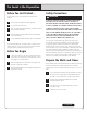


NOTE: A BLIND WALL CABINET FILLS THE VOID OF THE
CORNER WITH USABLE STORAGE. THE DOOR COMES PRE-
MOUNTED ON THE LEFT SIDE, BUT CAN BE MOVED TO THE
RIGHT DEPENDING ON YOUR DESIGN (SEE DIAGRAM A).
2.4
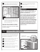
Using a level, make sure each cabinet is level and each
face frame (front of the cabinet) is flush with the adjacent
cabinet. A pry bar and shims can be used temporarily to get
everything level and plumb. (Figure 7)
NOTE: IT IS PARTICULARLY IMPORTANT TO INSTALL THE FIRST
CABINET LEVEL AND PLUMB, BOTH FROM SIDE-TO-SIDE AND
FROM FRONT-TO-BACK BECAUSE EACH ADDITIONAL CABINET
WILL BE ALIGNED WITH THE FIRST ONE.
NOTE: PLACE TALL CABINETS FOR SPACING, BUT DO NOT
ASSEMBLE.
WARNING
TO PROPERLY SECURE WALL CABINETS LARGER THAN
15” WIDE, AND TO REDUCE THE RISK OF CABINETS
FALLING AND CAUSING SERIOUS INJURY, USE AT LEAST 4
INSTALLATION SCREWS AND MAKE SURE THE SCREWS GO
INTO THE STUDS AT LEAST 1”.
2.5
In order to attach two cabinets together, you will need to
clamp them together first. Then, drill a
3
⁄32” pilot hole in
three places along the hinge side of the frame. Finally, drive
in the #8 x 2
1
⁄2” frame attachment (trim head) screws to
join the two cabinets. (Figure 8)
2.6
IMPORTANT: Check to make sure the frames are even and
plumb.
2.7
Continue for the remainder of the cabinets and fillers
following the layout provided by your designer.
2.8
Once all cabinets are pre-assembled on the floor, measure from
the corner to the first stud mark and transfer the measurement
to the inside of the cabinet to be installed. Repeat this step for
each and every stud. Now drill
7
⁄32” holes for mounting through
the top and bottom hanging rails inside of the cabinet
3
⁄4” down
from the top and
3
⁄4” up from the bottom. (Figure 9)
2.9
Fillers must also be pre-drilled and screwed into position.
Refer to STEP 4–INSTALL FILLERS… for more information
about measuring, cutting and installing fillers.
DIAGRAM A
Adjacent
wall cabinet
Blind wall cabinet
Filler –refer to your layout
for the appropriate filler
width and distance to
pull the cabinet from
the wall.
Figure 8
Frame
attachment
screws
Clamp face frames
together first
3
⁄32" pilot hole
Figure 7
Shim as required
Level
Shim as required
Shim as required
Temporary
support rails
Wall stud locations
Figure 9
Temporary
support rails
Transfer stud
locations to
wall cabinets
Assembled wall cabinets
Wall stud locations
There are two hanging rails across the
back of wall cabinets, one at the top and
one at the bottom. Drill through both
the top and bottom hanging rails at the
stud location.
3
⁄4" up from
bottom
3
⁄4" down
from top
6