welcoming • sophisticated • inspiring allen + roth® is a registered trademark of LF, LLC. All Rights Reserved. ITEM #0447705 VALDOSTA PORTABLE FAN MODEL #L1120H Español p. 10 ATTACH YOUR RECEIPT HERE Serial Number Purchase Date Questions, problems, missing parts? Before returning to your retailer, call our customer service department at 1-866-439-9800, 8 a.m. - 6 p.m., EST, Monday - Thursday, 8 a.m. - 5 p.m., EST, Friday. EB13334 Lowes.
TABLE OF CONTENTS Package Contents............................................................................................................... 3 Hardware Contents............................................................................................................. 4 Safety Information............................................................................................................... 4 Preparation .......................................................................................
PACKAGE CONTENTS A F D B C E PART A B C D E F G H I G H DESCRIPTION Downrod Assembly Coupling Cover Rod Clip Motor Body Wire Clip Coupling (Preassembled to the Motor Body (D)) Cross Pin (Preassembled to Coupling (F)) Clip (Preassembled to Coupling (F)) Coupling Screw (Preassembled to Coupling (F)) I QUANTITY 1 1 1 1 6 1 1 1 2 Lowes.
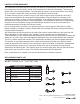
HARDWARE CONTENTS (shown actual size) AA BB Acorn Nut Set Screw Qty. 1 Qty. 1 SAFETY INFORMATION READ AND SAVE THESE INSTRUCTION • This fan is applicable only for gazebos or pagodas where a reliable mounting bracket is provided. • Ensure the hanging structure can support a minimum weight of 65 lbs. If you are not sure the hanging structure can support the weight, do not attempt to install this fan as it may fall and cause damage to the fan or personal injury.
PREPARATION Before beginning assembly of the product, make sure all parts are present. Compare parts with package contents list and hardware contents list. If any part is missing or damaged, do not attempt to assemble the product. Estimated Assembly Time: 45 minutes Tools Required for Assembly (not included): Philips Screwdriver, Step Ladder, Tape and Pliers.
ASSEMBLY INSTRUCTIONS 3. Insert downrod assembly (A) through coupling cover (B) into coupling (F). Make sure to align the hole in downrod assembly (A) with the hole in coupling (F). Install cross pin (G) through coupling (F) and downrod assembly (A). Insert clip (H) into cross pin (G) until it snaps into place. Tighten coupling screws (I) and slide the coupling cover (B) onto the motor body (D). 3 A A H I B F G D 4. Secure the wire from motor body (D) to the downrod assembly (A) with rod clip (C).
ASSEMBLY INSTRUCTIONS 6. Peel the backing off the adhesive tape stripes on the bottom of the wire clips (E). Attach the wire clips (E) as needed to the wall or ceiling and press gently. Clip the power cord to the wire clips (E). Plug the power cord into a ground 3-prong outlet. Once you restore power to the house, the fan is ready to use. 6 E OPERATING INSTRUCTIONS 1. The knob on the bottom of the fan operates the fan speed as follows: High, Medium, Low, and Off. 1 Knob Lowes.
CARE AND MAINTENANCE IMPORTANT: Shut off the main power supply before beginning any maintenance. Do not use water or a damp cloth to clean the ceiling fan. • Clean fan housing with only a soft brush or lint-free cloth to avoid scratching the finish. Clean blades with a lint-free cloth. • This product employs overload protection (fuse). A blown fuse indicates an overload or short-circuit situation.
LIMITED LIFETIME WARRANTY The manufacturer warrants this fan to be free from defects in workmanship and material present at time of shipment from the factory for life (with limitations) from the date of purchase. This warranty applies only to the original purchaser. The manufacturer agrees to correct such defect at no charge or, at our option, replace the ceiling fan with a comparable or superior model. To obtain warranty service, present a copy of your sales receipt as proof of purchase.
welcoming • sophisticated • inspiring allen + roth® es una marca registrada de LF, LLC. Todos los derechos reservados. ARTÍCULO #0447705 VENTILADOR PORTÁTIL VALDOSTA MODELO #L1120H ADJUNTE SU RECIBO AQUÍ Número de serie Fecha de compra ¿Preguntas, problemas, piezas faltantes? Antes de volver a la tienda, llame a nuestro Departamento de Servicio al Cliente al 1-866-439-9800, de lunes a jueves de 8 a.m. a 6 p.m., y los viernes de 8 a.m. a 5 p.m., hora estándar del Este. Lowes.
ÍNDICE Contenido del paquete ....................................................................................................... 12 Aditamentos ........................................................................................................................ 13 Información de seguridad ................................................................................................... 13 Preparación ....................................................................................................
CONTENIDO DEL PAQUETE A F D B C E PIEZA A B C D E F G H I G H I DESCRIPCIÓN Ensamble de la varilla Cubierta del acoplador Sujetador de la varilla Cuerpo del motor Sujetador de cables Acoplador (preensamblado en el cuerpo del motor (D)) Pasador cruzado (preensamblado en el acoplador (F)) Sujetador (preensamblado en el acoplador (F)) Tornillo para el acoplador (preensamblado en el acoplador (F)) CANTIDAD 1 1 1 1 6 1 1 1 2 Lowes.
ADITAMENTOS (se muestran en tamaño real) AA BB Tuerca ciega Tornillo de fijación Cant. 1 Cant. 1 INFORMACIÓN DE SEGURIDAD • • • • • • • • • • • • LEA Y GUARDE ESTAS INSTRUCCIONES Este ventilador es apto solo para gazebos o pagodas donde haya un soporte de montaje confiable. Asegúrese de que la estructura de donde va a colgar el ventilador pueda soportar un peso de mínimo de 29,48 kg.
PREPARACIÓN Antes de comenzar a ensamblar el producto, asegúrese de tener todas las piezas. Compare las piezas con la lista del contenido del paquete y la lista de aditamentos. No intente ensamblar el producto si falta alguna pieza o si estas están dañadas. Tiempo estimado de ensamblaje: 45 minutos Herramientas necesarias para el ensamblaje (no se incluyen): Destornillador Phillips, escalera de tijera, cinta y pinzas. INSTRUCCIONES DE ENSAMBLAJE 4.
INSTRUCCIONES DE ENSAMBLAJE 3. Introduzca el ensamble de la varilla (A) a través de la cubierta del acoplador (B) y en el acoplador (F). Asegúrese de alinear el orificio en el ensamble de la varilla (A) con el orificio en el acoplador (F). Instale el pasador cruzado (G) a través del acoplador (F) y el ensamble de la varilla (A). Inserte el sujetador (H) en el pasador cruzado (G) hasta que calce a presión en su lugar.
INSTRUCCIONES DE ENSAMBLAJE 6. Despegue el refuerzo de las tiras de cinta adhesiva en la parte inferior de los sujetadores de cables (E). Fije los sujetadores de cables (E) según sea necesario a la pared o el techo y presione con cuidado. Sujete el cable de alimentación con los sujetadores de cables (E). Enchufe el cable de alimentación en un tomacorriente con puesta a tierra de 3 clavijas. Una vez que vuelva a conectar la alimentación hacia la casa, el ventilador está listo para usarse.
CUIDADO Y MANTENIMIENTO IMPORTANTE: Antes de realizar cualquier trabajo de mantenimiento, desconecte el suministro de electricidad principal. No utilice agua ni un paño húmedo para limpiar el ventilador de techo. • Limpie la carcasa del ventilador solo con un cepillo suave o un paño sin pelusas para evitar rayar el acabado. Limpie las aspas con un paño sin pelusas. • Este producto posee protección contra sobrecargas (fusible). Un fusible quemado indica que se ha producido una sobrecarga o un cortocircuito.
GARANTÍA LIMITADA DE POR VIDA El fabricante garantiza que este ventilador no presenta defectos en los materiales ni en la mano de obra presentes en el momento del transporte desde la fábrica, por un período de por vida (con limitaciones) a partir de la fecha de compra. Esta garantía es válida solo para el comprador original. El fabricante acepta reparar dichos defectos sin cargo o, según nuestro criterio, reemplazar el ventilador de techo por un modelo comparable o superior.