welcoming • sophisticated • inspiring allen + roth® is a registered trademark of LF, LLC. All Rights Reserved. ITEM #0339207, 0339208, 0339209, 0339210, 0810375 PREMIUM WOOD TOWER MODEL#WSWS-WU1C, WSWS-WU1W WSWS-WU1P, WSWS-WU1S, WSWS-WU1G Français p. 14 ATTACH YOUR RECEIPT HERE Serial Number Español p. 27 Purchase Date Questions, problems, missing parts? Before returning to your retailer, call our customer service department at 1-866-439-9800, 8 a.m. – 8 p.m., EST, Monday - Friday. Lowes.
TABLE OF CONTENTS PACKAGE CONTENTS Camlock System Operation............................................................................................... 2 Package Contents............................................................................................................... 3 M C Hardware Contents...............................................................................................................4 J D Safety Information.............................................................
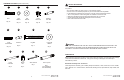
HARDWARE CONTENTS (shown actual size) AA CC BB Bolt SAFETY INFORMATION DD EE Lock Washer Flat Washer Large Cam Lock Medium Cam Bolt Qty. 12 Qty. 12 Qty. 34 Qty. 30 Please read and understand this entire manual before attempting to assemble, operate or install the product. • Do not allow children to climb or play in or around this product. • Use this unit for its intended purpose only. Do not use shelves as step ladder.
ASSEMBLY INSTRUCTIONS ASSEMBLY INSTRUCTIONS Base Assembly 4. From the back of the assembly, attach base panel right (I) to base panel back (K) using flat washers (CC), lock washers (BB) and bolts (AA). Tighten with Allen wrench (LL). Secure base panel top (J) with large cam locks (DD). 1 1. Insert medium cam bolts (EE) into base panel left (H), base panel right (I) and base panel top (J).
ASSEMBLY INSTRUCTIONS ASSEMBLY INSTRUCTIONS 7. From the back of the assembly, attach base panel left (H) to base panel back (K) using flat washers (CC), lock washers (BB) and bolts (AA). Tighten with Allen wrench (LL). Secure base panel top (J) with large cam locks (DD). 10. Insert wood dowels (FF) and large cam locks (DD) into hutch assembly. Attach hutch panel top (C), tightening large cam locks (DD) to secure assembly.
ASSEMBLY INSTRUCTIONS CARE AND MAINTENANCE Wall Hanging Installation 13 13. Using a stud finder, locate the edges of the wood studs. Find the center line of each stud and draw a vertical reference line on the wall over each one. Position installation template (N) at desired location on wall. • Periodically check to make certain all components are properly positioned, free from damage and firmly connected. • Use a soft, clean cloth that will not scratch the surface when dusting.
WARRANTY REPLACEMENT PARTS LIST This product (exclusive of shelves) is warranted to the original purchaser. If there is a failure in this unit due to defects in materials or workmanship, the manufacturer will repair or replace this item at our discretion without charge. Warranty is void if product has been assembled incorrectly, misused, abused by overloading, altered in any way or damaged due to accident.
welcoming • sophisticated • inspiring allen + roth® est une marque de commerce déposée de LF, LLC. Tous droits réservés.
TABLE DES MATIÈRES CONTENU DE L’EMBALLAGE Fonctionnement du système Camloc................................................................................. 15 Contenu de l’emballage....................................................................................................... 16 M C Quincaillerie incluse..............................................................................................................17 J D Consignes de sécurité.....................................................
QUINCAILLERIE INCLUSE (grandeur réelle) AA CC BB Boulon CONSIGNES DE SÉCURITÉ DD EE Rondelle de blocage Rondelle plate Grande attache Camloc Vis Camloc moyenne Qté : 12 Qté : 12 Qté : 34 Qté : 30 Qté : 12 GG HH Goujon de bois long Taquet pour tablette Tire-fond Qté : 34 Qté : 8 FF JJ KK • Ne laissez pas les enfants grimper ou jouer sur l’article ni autour de celui-ci. • Utilisez cet article uniquement pour l’usage auquel il est destiné.
INSTRUCTIONS POUR L’ASSEMBLAGE INSTRUCTIONS POUR L’ASSEMBLAGE Assemblage de la base 1. Insérez les vis Camloc moyennes (EE) dans le panneau gauche de la base (H), dans le panneau droit de la base (I) et dans le panneau supérieur de la base (J). 4. À partir de l’arrière de l’ensemble, fixez le panneau droit de la base (I) au panneau arrière de la base (K) à l’aide de rondelles plates (CC), de rondelles de blocage (BB) et de boulons (AA). Serrez les boulons à l’aide de la clé hexagonale (LL).
INSTRUCTIONS POUR L’ASSEMBLAGE INSTRUCTIONS POUR L’ASSEMBLAGE 7. À partir de l’arrière de l’ensemble, fixez le panneau gauche de la base (H) au panneau arrière de la base (K) à l’aide de rondelles plates (CC), de rondelles de blocage (BB) et de boulons (AA). Serrez les boulons à l’aide de la clé hexagonale (LL). Fixez le panneau supérieur de la base (J) au moyen de grandes attaches Camloc (DD). 10. Insérez des goujons en bois (FF) et de grandes attaches Camloc (DD) dans l’ensemble de l’étagère.
INSTRUCTIONS POUR L’ASSEMBLAGE ENTRETIEN Installation au mur 13. À l’aide d’un détecteur de montants, repérez les bordures des montants. Trouvez le centre de chaque montant et tracez une ligne de référence verticale sur le mur. Placez le gabarit pour l’installation (N) sur le mur à l’endroit désiré. Remarque : Le bas du gabarit pour l’installation (N) devrait être à une distance minimale de 80,01 cm du plancher.
GARANTIE LISTE DES PIÈCES DE RECHANGE La présente garantie n’est offerte qu’à l’acheteur initial (et ne s’applique pas aux tablettes). Si cet article présente des défauts de matériaux ou de fabrication, le fabricant choisira, à sa seule discrétion, de réparer ou de remplacer l’article sans frais.
welcoming • sophisticated • inspiring allen + roth® es una marca registrada de LF, LLC. Todos los derechos reservados. ARTÍCULO # 0339207, 0339208, 0339209, 0339210, 0810375 TORRE DE MADERA DE PRIMERA CALIDAD MODELO # WSWS-WU1C, WSWS-WU1W, WSWS-WU1P, WSWS-WU1S, WSWS-WU1G ADJUNTE SU RECIBO AQUÍ Número de serie Fecha de compra ¿Preguntas, problemas, piezas faltantes? Antes de volver a la tienda, llame a nuestro Departamento de Servicio al Cliente al 1-866-439-9800, de lunes a viernes de 8 a.m. a 8 p.m.
ÍNDICE CONTENIDO DEL PAQUETE Funcionamiento del sistema de cerrojo de leva................................................................... 28 Contenido del paquete........................................................................................................ 29 M C Aditamentos........................................................................................................30 J D Información de seguridad................................................................................
ADITAMENTOS (se muestran en tamaño real) AA CC BB Perno INFORMACIÓN DE SEGURIDAD DD EE Arandela de seguridad Arandela plana Cerrojo de leva grande Perno de leva mediano Cant. 12 Cant. 12 Cant. 34 Cant. 30 Cant. 12 GG HH Espiga grande de madera Pasador de estante Tirafondo Cant. 34 Cant. 8 FF JJ Cant. 4 LL • No permita que los niños se suban al producto o que jueguen cerca de él. • Use esta unidad solo para el fin para el cual se diseñó.
INSTRUCCIONES DE ENSAMBLAJE INSTRUCCIONES DE ENSAMBLAJE Ensamblaje de la base 4. En la parte posterior del ensamblaje, fije el panel de base derecho (I) al panel de base posterior (K) con las arandelas planas (CC), las arandelas de seguridad (BB) y los pernos (AA). Apriete con una llave de tuercas Allen (LL). Asegure el panel de base superior (J) con los cerrojos de leva grandes (DD). 1 1.
INSTRUCCIONES DE ENSAMBLAJE INSTRUCCIONES DE ENSAMBLAJE 7. Desde la parte posterior del ensamblaje, fije el panel de base izquierdo (H) al panel de base posterior (K) con las arandelas planas (CC), las arandelas de seguridad (BB) y los pernos (AA). Apriete con una llave de tuercas Allen (LL). Asegure el panel de base superior (J) con los cerrojos de leva grandes (DD). 10. Introduzca las espigas de madera (FF) y los cerrojos de leva grandes (DD) en el ensamblaje de la repisa.
INSTRUCCIONES DE ENSAMBLAJE CUIDADO Y MANTENIMIENTO Instalación colgante para pared 13. Con un detector de vigas, localice los bordes de las vigas de madera. Localice la línea central de cada viga y trace una línea vertical como referencia en la pared sobre cada una. Coloque la plantilla de instalación (N) en el lugar deseado sobre la pared. 13 Viga de madera Nota: la parte inferior de la plantilla de instalación (N) debe quedar a no más de 31-1/2 pulg/80,01 cm del piso.
GARANTÍA LISTA DE PIEZAS DE REPUESTO La garantía de este producto (exclusiva de las repisas) es válida para el comprador original. Si esta unidad presenta alguna falla debido a defectos en los materiales o la mano de obra, el fabricante reemplazará o reparará este artículo sin cargos y a su discreción. La garantía se anula si el producto no se ensambló correctamente y debido al mal uso, abuso por sobrecarga, modificación de cualquier tipo o daños producidos por un accidente.