
User Manual


8
8
RS232 Serial Data Interface
The RS232 serial data interface comprises a 3-wire arrangement, consisting of transmit
(TxD/yellow), receive (RxD/green), and ground (GND/white). This interface can be
configured for a variety of communications parameters, but is factory configured with
default settings of 9600 bits/second, no parity, 8 bits/word, and 1 stop bit (“9600N81”),
and no flow control. To determine the required settings, refer to the interface
requirements for the data recording application that is being used with the Panel
Reader. To change these default settings, please see “Configuration Options” on pages
15 and 16 of this guide.
Serial data appears on the Panel Reader’s TxD connection in ASCII format, and is
compatible with most PC terminal emulator programs, such as Hyperterminal®.
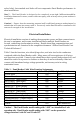
Configuration options provide flexible parsing and formatting of transponder ID code
information (see “Configuration Options” on pages 15 and 16 of this guide). The
default formats for ISO transponder tag types are listed in Table 2 on page 2 of this
guide.
RS422/RS485 Serial Data Interface
The Panel Reader’s RS422/RS485 serial data interface comprises a balanced 4-wire
(RS422) or balanced 2-wire (RS485) arrangement, which is capable of being used in
any of several wiring configurations. The balanced nature of this interface provides the
ability to achieve long data communications cable lengths of up to 1500 meters (5000
feet) at the maximum communications data rate of 57,600 bits/second.
An excellent technical guide to RS422/RS485 communications can be found on, and
downloaded from, B&B Electronics’ Internet web-site at:
http://www.bb-elec.com/tech_articles/rs422_485_app_note/table_of_contents.asp
Users who are planning to connect several Panel Readers on an RS422/RS485 bus
should consult the Allflex Panel Reader User Technical Reference for further
information about serial data communications and bus addressing requirements.
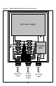
Installation and Connection with the Allflex AC/DC Power Unit
Electrical installation consists only of connecting power and data wires to the terminal
block in the power supply box, or connecting these wires in an alternate manner
conducive to the user’s application. Figure 3 illustrates the Allflex P/N 930014-002
AC/DC Power Unit terminal blocks where power and data wires are connected, and
shows the wire color code and functions. All connections should be made with power
turned off to the Allflex Power Supply and to the user’s PC/data recording equipment.
Once the Panel Reader cable is routed in an acceptable and protected manner to the
location where the power supply enclosure is mounted, installation is as follows,
referring to Figures 3 and 4: