
User's Manual


computer displays, for example – can interfere with the transmission and reception of RFID
signals, and consequently reduce reading distance.
Eartag/Reader Interference - Multiple eartags within the sensing range of the reader, or
other readers emitting excitation energy in the immediate vicinity can adversely affect the
reading performance or prevent operation of the Panel Reader.
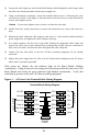
Panel Reader Read Zone Geometry
The read zone is the 3-dimensional space within which an eartag can be read when held
in a static and optimum orientation. Figure 5 approximates the Panel Reader’s read
zone in a 2-dimension perspective, as viewed from either the side or top, and illustrates
eartag orientation for maximum and null reading. The read zone is symmetrical around
a centerline that bisects the plane of the Panel Reader. Optimum read distance is
achieved when the Panel Reader’s magnetic field lines intersect the surface of the
eartag perpendicularly. More practicably, the eartag’s read range is maximized when
the eartag’s axis is perpendicular to the midpoint of the Panel Reader’s planar surface.
As the eartag is shifted from midpoint toward an edge of the Panel Reader, maximum
read distance is usually achieved by tilting the eartag so as to maintain perpendicularity
with the magnetic field lines as shown in Figure 5.
Figure 5 - Panel Reader Read Zone and Tag Orientation
Eartag
Optimum Orientation
Eartag
Optimum Orientation
Eartag
Null Orientation
Eartag
Null Orientation
Eartag
Oblique Orientation
Antenna Coil
Winding
Panel Reader
(Top Cutaway
View)
Magnetic
Field Line
Read Zone
Boundary
12
12