
User's Manual


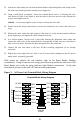

Loosen the cable clamp nut, and feed the Panel Reader cable through the cable clamp so that
the cable outer sheath protrudes into the power supply box.
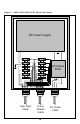
Using a small blade screwdriver, loosen the terminal block screws. Following the color
code shown in Table 3 and Figure 4, feed the ends of the wires into the cavity beneath the
screws, and retighten screws.
Caution - Do not over-tighten screws, as they can shear the wire ends.
Double check the wiring connections to ensure all connections are correct and screws are
snug.
Position the cable within the cable clamp so that about ¼” of the sheath extends inside the
power supply box, and tighten the cable clamp nut securely.
In a similar manner, feed the user’s data cable through the designated cable clamp and
connect the cable wires to the terminal block, ensuring that all data wires are connected to
their correct locations. Position the cable and tighten the cable clamp nut.
Connect the user data cable to the user PC/data recording equipment (if not already
connected.
Plug-in the power supply box AC cable to an AC mains outlet, making sure the AC power
mains source is properly grounded.
With power on, observe the red indicator light on the Panel Reader flashing
continuously. Using at least one test eartag, place the eartag within the read zone of the
Panel Reader and verify the green indicator light flashes continuously. Verify that
serial data is present on the user’s PC/data recording equipment.
Figure 3 - AC Power Unit Terminal Block Wiring Diagram
+6 VDC
Ground
Data Out
Data In
Data Gnd
Shield
TX+
TX-
RX+
RX-
Sync +
Sync-
R
S
4
2
2
R
S
2
3
2
RED
BLK
YEL
GRN
WHT
SHLD
CYN
GRY
ORN
BRN
BLU
VIO
PANEL
READER
CABLE
Terminal Block Wiring Diagram
9
9