
User manual


Rev Australasia V2.3 12/04
35 35
The table below shows how the cables should connect from one end to the other.
Electronic Circuit Board Military
Connector
9 pin D Connector
Transmit (TxD) Pin A Pin 2
Receive (RxD) Pin B Pin 3
Signal Ground (GND) Pin D Pin 5
Pin C (not used)
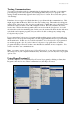
You can test these connections using the Multi-meter.
On the dial of the meter select the Ω
s
cale. If your meter has an audible
beeper, select that setting, if not select the
lowest value in the scale.
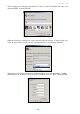
Insert the test leads into the meter, the
Black lead connects to the COM socket
and the Red lead connects to the socket
showing the Ω Omega symbol.
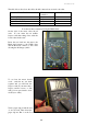
To see how the meter should
work – touch the two test leads
together and you will hear the
beeper sound (if your meter has a
beeper) and the screen, or dial
will go from open circuit to short
circuit (zero ohms).
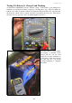
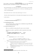
Twist a paper clip around the end
of one test lead. Then insert the
paper clip into Pin 2 on the D connector. From the table above, you can see that Pin 2