AllFuel HST Model AF-HST 6” & 8” Diameter Installation Instructions A MAJOR CAUSE OF CHIMNEY RELATED FIRES IS FAILURE TO MAINTAIN REQUIRED CLEARANCES (AIR SPACES) TO COMBUSTIBLE MATERIALS. IT IS OF THE UTMOST IMPORTANCE THAT THIS CHIMNEY BE INSTALLED ONLY IN ACCORDANCE WITH THESE INSTRUCTIONS. Note: Read through all these instructions before beginning your installation.
PG 2 For the most up-to-date installation instructions, planning guides, and video instructions visit our Learning Center at https://allfuelhst.com/pages/learning-center-home Contents Clearances…………………………………………………………………………….....3 Permits………………………………………………………………………………..….3 Model AF-HST Applications………………………………………………………...….3 Chimney Diameter…………………………………………………………………...….3 Chimney Height……………………………………………………………………..…..3 Chimney Placement………………………………………………………………….....
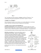
PG 3 CLEARANCES Always allow at least a 2-inch clearance between Model AF-HST chimney pipe and any combustible materials. Never fill any required clearance space with insulation or any other materials. Combustible materials include lumber, plywood, sheetrock, plaster and lath, furniture, curtains, electrical wiring and building insulation.
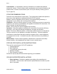
PG 4 The Tee Support can hold a maximum of 50 feetof AllFuel HST Chimney. The required parts and general configuration are as shown in Figures 21 and 22. CHIMNEY PLACEMENT When deciding the location of your chimney, try to avoid modifications to roof beams, trusses, wall studs, and other structural components of the building.
PG 5 Cold Climates: In cold climates, chimneys mounted on an outside wall should be enclosed in a chase. Exterior chases reduce condensation and creosote formation, and enhance draft. Include an access door by the Tee Cap for chimney cleaning (refer to Fig 21, page 16). STOVE RECOMMENDATIONS Follow the stove manufacturer’s instructions. The requirements stated below pertain to all stoves or other appliances installed with Model AF-HST systems.
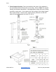
PG 6 2. Frame Support Opening: Drop a plumb bob to the center of the appliance’s flue outlet and mark the center point on the ceiling. Refer to Table 1for specific framing and clearance dimensions. Mark appropriate cutting lines on the ceiling around the center point. Cut a square hole in the ceiling for the Ceiling Support Box to pass through. Frame a level, square opening centered over the hole which you have cut between the joists (Fig 3 & 4). AllFuel HST Inc www.allfuelhst.
PG 7 3. Flat Ceiling Support Box Installation: For a flat ceiling installation use the Square Ceiling Support Box and Trim. The bottom of the Square Ceiling Support Box must extend at least 2 inches below the finished ceiling (measured to the bottom of the box not including the round adapter section) (Fig 5). Level the Support Box and secure it to the framing using at least three 8-penny nails per side (min. of 12 total). Alternatively, you may use 1-½” #8 wood screws (min. of 12 total), instead of nails.
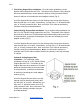
PG 8 4. Multi-Story Installation - Frame Openings: Frame openings in each ceiling or floor above the Support Box (Fig 6). These openings are to hold the Firestop Radiation Shields and Attic Insulation Shields. Locate each opening by dropping a plumb bob to the four corners of the opening below. Maintain the minimum clearances and dimensions as specified in Table 1. If Elbows must be used to avoid an obstruction, refer to the Offset Elbow Installation section. AllFuel HST Inc www.allfuelhst.
PG 9 5. Cut Roof Opening: Cut an opening in the roof directly above the opening below and at least 4 inches larger than the chimney’s outside diameter to provide at least a 2 inch clearance all around the chimney. The chimney must be centered within this opening and maintain the 2 inch clearance to combustibles. 6. Install Radiation Shield: A Radiation Shield is required in multistory installations at each floor penetration above that where the Support Box is located.
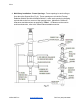
PG 10 attic areas where this shield cannot fit, a Square Ceiling Support Box, (which are available in heights of 11”, 24”, and 36”), can be used instead of an Attic Insulation Shield, provided it reaches through the roof; refer to the Roof Supported Installation section on page 14. If the chimney is fully enclosed through the attic, an Attic Insulation Shield is not required. Where the chimney passes into the attic, install the Attic Insulation Shield as follows: a.
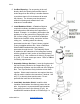
PG 11 pipe, which is exposed to the weather (Fig 10 & 11). Slide the Storm Collar down over the chimney to the top of the Roof Flashing. Tighten and seal the Storm Collar against the sealant. After installing sufficient Chimney Sections to meet the height requirement (Fig 1), attach the Chimney Cap on top of the chimney by holding the collar of the cap and twist locking it clockwise onto the chimney. Do not hold the upper portion of the cap and twist, as this may damage the cap.
PG 12 Chimney Section below, and align it for the offset. Refer to Table 2to determine the required offset length and attach an appropriate length (or lengths) of Chimney Section(s) above the Elbow. Note: maximum of two chimney sections can be connected between Elbows. The maximum length of chimney pipe between elbows is not to exceed 72”. Attach the second Elbow above the Chimney Section to complete the offset (Fig 12). 2.
PG 13 Table 2 Elbow Offset Chart EXTENDED ROOF BRACE INSTALLATION If the chimney extends more than 5 feet above the roofline, an Extended Roof Brace must be installed at every 5-foot increment of chimney height above the roofline, leaving nor more than 5 feet of chimney extending above the last Extended Roof Brace. The Extended Roof Brace consists of the Pipe Band, the Adjustable Legs, and the Roof Brackets. 1.
PG 14 provided in the outer leg where the outer and inner halves overlap. Use a ¼” drill bit to drill through the inner leg at that location. Use the nut & bolt provided to pin the Adjustable Legs in position. 3. Install Roof Bracket: Mount the two Brackets where each of the adjustable legs meets the roof, using (6) 1” roofing nails per bracket. Seal the nail heads carefully with a non-hardening, waterproof sealant.
PG 15 to Table 1 on page 6 for clearance and framing specifications. If installing through a cathedral ceiling refer to Fig 15, the hole is cut directly in the roof. 3. Install Square Ceiling Support Box: Slip the Square Ceiling Support Box into the framed opening so the square portion projects at least 2 inches below the finished ceiling and rafters, and extends above the ceiling to framing or decking materials that it can be nailed to.
PG 16 A Roof Support Bracket is used in installations where there is a cathedral ceiling and a Square Ceiling Support is notdesired (Often used in unfinished buildings, workshops, garages, etc). The Roof Support Bracket allows the AF-HST to come down into the room below the level of the ceiling (Fig 17). The Roof Support Bracket can support a maximum of 45 feet of AF-HST total, and a maximum of 20 feet below the support. 1.
PG 17 3. Determine how much AF-HST chimney will be extending into the room (minimum of 3” below the finished ceiling). Be sure to maintain the proper clearance to combustibles (walls and ceilings) for the connector pipe. Once you have identified the proper height for your installation, attach the Roof Support Band to the Chimney Section by tightening the bolt and secure it with supplied hardware. 4. Attach desired length of Chimney Sections above and below the roof level (max.
PG 18 1. Cut and frame opening to provide a minimum of 2” clearance on all sides of the chimney. Be sure to maintain the proper clearance to combustibles for the connector pipe. 2. Bolt on the Roof Support Brackets to the Roof Support Band using the supplied hardware. Attach the Roof Support Brackets to the floor joists using (4) 8-penny nails or (4) #8, 1-½” screws per side (Fig 18). 3.
PG 19 TEE-SUPPORTED INSTALLATIONS Tee-Supported installations are used when passing through a wall to an outside chimney. The Tee Support can hold a maximum of 50 feet of AF-HST chimney. The required parts and general configuration are as shown in Figures 20 & 21. 1. Place Appliance: Position the appliance according to the manufacturer’s instructions. It is a good idea to try to position the appliance so it will allow the chimney to line up centered between studs. 2.
PG 20 the female coupler of the Tee. Lock securely into the Tee by twisting clockwise. Place the assembled Wall Support against the wall (plate up) directly below the insulated coupling section of the Wall Support. Tighten the insulated coupling section and the support plate with the supplied lag screws (#14 x 2”). Then secure the whole Base Wall Support assembly onto the wall using #14 x 2” wood screws through the pre-punched slots in each bracket.
PG 21 7. AllFuel HST Inc www.allfuelhst.
PG 22 AllFuel HST Inc www.allfuelhst.
PG 23 MASONRY FIREPLACE INSTALLATIONS 1. Determine Chimney Size: Use table 3 to determine the correct diameter chimney for your fireplace. 2. Mount Anchor Plate: Chimneys for masonry fireplaces begin with an Anchor Plate. Make sure the surface of the masonry chimney has a level surface on which to attach the Anchor Plate. If the top of the masonry does not have a level surface, then you will need to modify the masonry accordingly.
PG 24 AllFuel HST Inc www.allfuelhst.
PG 25 ZERO-CLEARANCE FIREPLACE INSTALLATIONS 1. Manufacturer's Instructions: Carefully read and comply with the manufacturer’s installation instructions for your fireplace. Be sure that AllFuel HST is approved for use with your appliance. 2. Anchor Plate:Attach an Anchor Plate to the fireplace top with (4) ⅝” sheet metal screws (Fig 27). Check with the appliance manufacturer about the use of high temperature sealants. 3.
PG 26 CHIMNEY MAINTENANCE 1. Creosote and Soot: When wood is burned slowly, it produces tar and other organic vapors, which combine with expelled moisture to produce creosote. The creosote vapors conscience in the relatively cool chimney flue of a slow-burning fire. As a result, creosote residue accumulates on the flue lining. When ignited, this creosote makes an extremely hot fire, known as a chimney fire. 2. Access: Chimneys must be installed so that access is provided for inspection and cleaning. 3.
PG 27 chimney will help to increase chimney life. 9. Creosote Formation: AllFuel HST assumes no liability for any structure damage or roof contamination as the result of creosote formation. It is the owner’s responsibility to comply with inspection and cleaning requirements as described in these instructions, and those of the appliance manufacturer. 10.