
Service manual


F238006 71
Section 5 Service Procedures
To reduce the risk of electrical shock, fire, explosion, serious injury or death:
• Disconnect electrical power to the washer-extractor before servicing it.
• Close the gas shut-off valve to the washer-extractor (when applicable) before servicing it.
• Never start the washer-extractor with any guards/panels removed.
• Whenever ground wires are removed during servicing, these ground wires must be
reconnected to ensure that the washer-extractor is properly grounded.
W461R1
WARNING
© Copyright, Alliance Laundry Systems LLC – DO NOT COPY or TRANSMIT
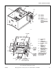
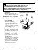
23. COMPUTER TEST PROCEDURE
With its fuse board, the WE-6 programmable
computer is easier to maintain than other controls.
The following procedures should help eliminate
problems and determine if components are not
functioning properly. Refer to Figure 2.
Test equipment required:
• 20K OHM/Volt AC-DC voltmeter.
• Wiring diagram, WE-6 (supplied with the
washer-extractor).
Computer Test Procedure
a. Power up the washer-extractor:
(1) When AC power is turned on, the display
should flash “POWER”/“WAIT”
alternately. After 90 seconds, the display
should read “NEXT 00.”
(2) The door unlock solenoid should function if
the door unlock button is pressed.
(3) If tests 1 and 2 are positive, go to Step c.
b. If the computer does not read “NEXT” or does
not illuminate, refer to the “WE-6 Control Has
No Visible Display” flowchart.
c. If the computer reads “NEXT”:
NOTE: Press the center of the keys, applying only
enough pressure to activate them.
(1) Test the keyboard, first with the keymode
switch (located on the left side of the
control module) in the “RUN” position. A
beep tone should sound as each key is
pressed. Press each of the keys except the
“START” key and listen for the beep. After
pressing all of the keys (except “START”),
press “3” and “9,” then press “START.”
The display should flash “NCYC 39” for 3
seconds and then return to “NEXT00.”
(2) When “DISPLAY TEMP” is pressed and
held, the computer display should change to
show the temperature inside of the sump.
When the key is released, the display
should return to the previous read-out.
(3) Turn the keymode switch to “PROGRAM”
and press “EDIT/CYCLE.” The read-out
should display “DCYC--.”
(4) Press “CLEAR/STOP.” The display should
return to “-CYC 00.”
(5) Return the keymode switch to the “RUN”
position.
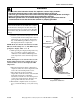
d. If the keyboard does not function as above:
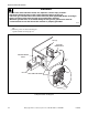
(1) Check the plug (J-3) at the bottom center of
computer board for proper installation.
Refer to Figure 4.
(2) If the plug is intact and is installed
correctly, proceed to Paragraph 25.
To reduce the risk of electrical shock, never
touch terminals or components of the AC
drive unless the power is disconnected and
the “CHARGE” indicator LED is off. The AC
drive retains potentially deadly voltage for
some time after the power is disconnected.
Tampering with the AC drive will void the
warranty. There are no user-serviceable
parts inside of the AC drive.
DANGER
To reduce the risk of injury, attempt no entry
until the basket has come to a complete
stop.
DANGER
Serious shock may occur. Open the primary
disconnect switch before attempting any
repairs.
WARNING