Basic Installation/Operation Washer-Extractors Cabinet Freestanding Keep These Instructions for Future Reference. (If this machine changes ownership, this manual must accompany machine.) www.comlaundry.com Part No.
Basic Installation/Operation Table of Contents Introduction......................................................................................... Model Identification ............................................................................. Safety Information.............................................................................. Explanation of Safety Messages........................................................... Important Safety Instructions .............................................
Basic Installation/Operation Introduction Model Identification Information in this manual is applicable to these models: 2 HX18PV HX100PV SX25PV SX135PV UX33PV UX100PV HX25PV HX135PV SX35PV SX165PV UX35PV UX135PV HX35PV HX165PV SX55PV SX200PV UX40PV UX165PV HX55PV HX200PV SX75PV UX18PV UX55PV UX200PV HX75PV SX18PV SX100PV UX25PV UX75PV © Copyright, Alliance Laundry Systems LLC – DO NOT COPY or TRANSMIT 9001014
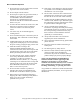
Basic Installation/Operation Safety Information Explanation of Safety Messages Precautionary statements (“DANGER,” “WARNING,” and “CAUTION”), followed by specific instructions, are found in this manual and on machine decals. These precautions are intended for the personal safety of the operator, user, servicer, and those maintaining the machine. DANGER DANGER indicates the presence of a hazard that will cause severe personal injury, death, or substantial property damage if the danger is ignored.
Basic Installation/Operation 9. Do not install or store the washer where it will be exposed to water and/or weather. 10. Do not tamper with the controls. 11. Do not repair or replace any part of the washer, or attempt any servicing unless specifically recommended in the user-maintenance instructions or in published user-repair instructions that the user understands and has the skills to carry out. 12.
Basic Installation/Operation WARNING CAUTION This machine must be installed, adjusted, and serviced by qualified electrical maintenance personnel familiar with the construction and operation of this type of machinery. They must also be familiar with the potential hazards involved. Failure to observe this warning may result in personal injury and/or equipment damage, and may void the warranty. SW004 IMPORTANT: Ensure that the recommended clearances for inspection and maintenance are provided.
Basic Installation/Operation Operator Safety Do not bypass any safety devices in the machine. WARNING WARNING NEVER insert hands or objects into basket until it has completely stopped. Doing so could result in serious injury. SW012 To ensure the safety of machine operators, the following maintenance checks must be performed daily: Never operate the machine with a bypassed or disconnected balance system.
Basic Installation/Operation Specifications and Dimensions General Specifications Model 18 25 33 35 40 Overall width 660 mm (26 in.) 660 mm (26 in.) 780 mm (30.71 in.) 783 mm (30.8 in.) 780 mm (30.71 in.) Overall height 1031 mm (40.6 in.) 1031 mm (40.6 in.) 1376 mm (54.15 in.) 1194 mm (47 in.) 1376 mm (54.15 in.) Overall depth 780 mm (30.7 in.) 870 mm (34.3 in.) 840 mm (33.07 in.) 960 mm (37.8 in.) 940 mm (37.01 in.) Net weight † 211 kg (465 lb.) 236 kg (520 lb.) 368 kg (811.
Basic Installation/Operation (continued) General Specifications Model 18 25 33 35 40 1 1 1 1 1 0.75 kW (1 HP) 0.75 kW (1 HP) 2.2 kW (2.95 HP) 1.5 kW (2 HP) 2.2 kW (2.
Basic Installation/Operation General Specifications Model 55 75 100 135 165 200 Overall width 900 mm (35.4 in.) 1060 mm (41.8 in.) 1200 mm (47.3 in.) 1200 mm (47.3 in.) 1300 mm (51.8 in.) 1300 mm (51.8 in.) Overall height 1544 mm (60.8 in.) 1560 mm (61.4 in.) 1920 mm (75.6 in.) 1920 mm (75.6 in.) 2100 mm (82.7 in.) 2100 mm (82.68 in.) Overall depth 1016 mm (40 in.) 1168 mm (46 in.) 1330 mm (52.4 in.) 1500 mm (59.1 in.) 1620 mm (63.8 in.) 1808 mm (71.18 in.
Basic Installation/Operation (continued) General Specifications Model 55 75 100 135 165 200 1 1 1 1 1 1 3 kW (4 HP) 4 kW (5.4 HP) 5.5 kW (7.4 HP) 7.5 kW (10 HP) 11.
Basic Installation/Operation 5 18: 787 mm (31 in.) 25: 884 mm (34.8 in.) 1031 mm (40.6 in.) 1011 mm (39.8 in.) 518 mm (20.4 in.) 279 mm (11 in.) 486 mm (19.13 in.) 660 mm (26 in.) 18: 560 mm (22.05 in.) 25: 660 mm (25.98 in.) CFD530N CFD530 N 229 mm (9 in.) 8 152 mm (6 in.) 74 mm (2.9 in.) 4 CFS464N CFS464N 1 2 3 140 mm (5.5 in.) 7 6 158 mm (6.2 in.) 780 mm (30.7 in.) 881 mm (34.7 in.) 742 mm (29.2 in.) 9 41 mm (1.6 in.) 10 389 mm (15.3 in.) 181 mm (7.1 in.) 51 mm (2 in.
Basic Installation/Operation 220 mm (8.66 in.) 279 mm (10.98 in.) 1011 mm (39.8 in.) 1038 mm (40.87 in.) 11 33 mm (1.3 in.) 33 mm (1.3 in.) 65 mm (2.56 in.) 530 mm (20.87 in.) 30 mm (1.18 in.) 65 mm (2.56 in.) 660 mm (25.98 in.) 18: 670 mm (26.38 in.) 25: 770 mm (30.31 in.) CFD521N 226 mm (8.9 in.) 151 mm (5.94 in.) 75 mm (2.95 in.) CFD521N 1 2 3 4 18: 590 mm (23.23 in.) 25: 690 mm (27.16 in.) 65 mm (2.72 in.) 18: 727 mm (28.62 in.) 25: 827 mm (32.56 in.) 5 10 30 mm (1.18 in.
Basic Installation/Operation 88 mm (3.47 in.) 472 mm (18.58 in.) 1376 mm (54.15 in.) 1348 mm (53.07 in.) 220 mm (8.66 in.) 50 mm (1.97 in.) 680 mm (26.77 in.) 780 mm (30.71 in.) 50 mm (1.97 in.) 34 mm (1.34 in.) 86.5 mm (3.41 in.) CFD537N CFD537N 332 mm (13.05 in.) 267 mm (10.49 in.) 202 mm (7.93 in.) 105 mm (4.13 in.) 1 2 4 665 mm (26.18 in.) 733 mm (28.86 in.) 753 mm (29.65 in.) 34 mm (1.34 in.) CFD538N CFD538N 3 5 6 7 10 1.38 in. (35 mm) 4.3 in. (109 mm) 185 mm (7.29 in.) 1015 mm (39.
Basic Installation/Operation 5 960 mm (37.8 in.) 1194 mm (47 in.) 1176 mm (46.3 in.) 620 mm (24.4 in.) 394 mm (15.5 in.) 639 mm (25.16 in.) 782 mm (30.8 in.) 770 mm (30.31 in.) CFD531N CFS467N CFS467N 328 mm (12.9 in.) CFD531N 264 mm (10.4 in.) 89 mm (3.5 in.) 3 1 2 155 mm (6.1 in.) 4 7 6 1041 mm (41 in.) 8 10 934 mm (36.75 in.) 965 mm (38 in.) 1001 mm (39.4 in.) 889 mm (35 in.) 9 508 mm (20 in.) 203 mm (8 in.) 112 mm (4.4 in.
Basic Installation/Operation 11 220 mm (8.66 in.) 376 mm (14.78 in.) 1202 mm (47.32 in.) 1176 mm (46.3 in.) 88 mm (3.47 in.) 34 mm (1.34 in.) 66 mm (2.6 in.) 34 mm (1.34 in.) 66 mm (2.6 in.) 648 mm (25.51 in.) 780 mm (30.71 in.) CFD524N 765 mm (30.12 in.) 860 mm (33.86 in.) 82 mm (3.23 in.) CFD524N 332 mm (13.05 in.) 267 mm (10.49 in.) 202 mm (7.93 in.) 105 mm (4.13 in.) 9 36.5 mm (1.44 in.) 916 mm (36.06 in.) 36.5 mm (1.44 in.) CFD525N CFD525N 1 3 2 10 4 5 8 6 109.2 mm (4.3 in.
Basic Installation/Operation 88 mm (3.47 in.) 472 mm (18.58 in.) 1376 mm (54.15 in.) 1348 mm (53.07 in.) 220 mm (8.66 in.) 680 mm (26.77 in.) 50 mm (1.97 in.) 50 mm (1.97 in.) 780 mm (30.71 in.) 34 mm (1.34 in.) 86.5 mm (3.41 in.) CFD537N CFD537N 332 mm (13.05 in.) 267 mm (10.49 in.) 202 mm (7.93 in.) 105 mm (4.13 in.) 1 2 4 765 mm (30.12 in.) 833 mm (32.8 in.) 853 mm (33.58 in.) 34 mm (1.34 in.) CFD538N CFD538N 3 5 6 10 7 35 mm (1.38 in.) 109 mm (4.3 in.) 185 mm (7.29 in.) 1015 mm (39.
Basic Installation/Operation 5 1016 mm (40 in.) 1544 mm (60.8 in.) 1499 mm (59 in.) 859 mm (33.8 in.) 559 mm (22 in.) 740 mm (29.13 in.) 900 mm (35.43 in.) 830 mm (32.68 in.) 102 mm (4 in.) CFS470N CFD509N CFS470N CFD509N 91 mm (13.6 in.) 254 mm (10 in.) 252 mm (9.9 in.) 158 mm (6.2 in.) 2 3 4 99 mm (3.9 in.) 1 6 191 mm (7.5 in.) 1389 mm (54.7 in.) 11 1283 mm (50.5 in.) 8 36 mm (1.4 in.) 721 mm (28.4 in.) 165 mm (6.5 in.) 165 mm (6.5 in.) 9 10 104 mm (4.1 in.) 104 mm (4.1 in.
Basic Installation/Operation 5 1168 mm (46 in.) 1575 mm (62 in.) 853 mm (33.6 in.) 1532 mm (60.3 in.) 559 mm (22 in.) 102 mm (4 in.) 870 mm (34.25 in.) 1060 mm (41.73 in.) 488 mm (19.2 in.) CFD510N 960 mm (37.8 in.) CFD510N 366 mm (14.4 in.) CFS473N CFS473N 246 mm (9.7 in.) 2 3 4 229 mm (9 in.) 94 mm (3.7 in.) 1 175 mm (6.9 in.) 6 1407 mm (55.4 in.) 7 11 1315 mm (51.75 in.) 8 43 mm (1.7 in.) 582 mm (22.9 in.) 170 mm (6.7 in.) 10 9 104 mm (4.1 in.) CFS474N 104 mm (4.1 in.
Basic Installation/Operation 100: 1331 mm (52.4 in.) 135: 1506 mm (59.3 in.) 6 1951 mm (76.8 in.) 960 mm (37.8 in.) 648 mm (25.5 in.) 102 mm (4 in.) 1040 mm (40.94 in.) 1200 mm (47.24 in.) CFD511N CFD511N 100: 1010 mm (39.76 in.) 305 mm (12 in.) 2362 mm (9.3 in.) 135: 1185 mm (46.65 in) CFS476N CFS476N 175 mm (6.9 in.) 89 mm (3.5 in.) 114 mm (4.5 in.) 104 mm (4.1 in.) 165 mm (6.5 in.) 2 3 5 170 mm (6.7 in.) 51 mm (2 in.) 249 mm (9.8 in.) 1 221 mm (8.7 in.) 4 9 7 1575 mm (62 in.
Basic Installation/Operation 1620 mm (63.8 in.) 6 2100 mm (82.7 in.) 1020 mm (40.2 in.) 641 mm (25.25 in.) 1140 mm (44.9 in.) 1300 mm (51.2 in.) 102 mm (4 in.) CFD511N CFD511N 360 mm (14.25 in.) 273 mm (10.75 in.) 1185 mm (46.7 in.) 198 mm (7.8 in.) CFD15N CFD15N 122 mm (4.8 in.) 114 mm (4.5 in.) 114 mm (4.5 in.) 2 172 mm (6.75 in.) 35 51 mm (2 in.) 197 mm (7.75 in.) 260 mm (10.24 in.) 1 221 mm (8.7 in.) 4 9 7 1854 mm (73 in.) 13 12 8 10 696 mm (27.4 in.) 254 mm (10 in.
Basic Installation/Operation 6 56.5 mm (2.23 in.) 2100 mm (82.7 in.) 993 mm (39 in.) 603 mm (23.75 in.) 44 mm (1.73 in.) 81 mm (3.19 in.) 1138 mm (44.8 in.) 272 mm (10.71 in.) 81 mm (3.19 in.) 1365 mm (53.74 in.) 1453 mm (57.2 in.) 175.2 mm (68.96 in.) 1300 mm (51.18 in.) 44 mm (1.73 in.) 26.5 mm (1.04 in.) CFD534N CFD533N CFD533N CFD534N 408 mm (16.06 in.) 323 mm (12.72 in.) 248 mm (9.76 in.) 173 mm (6.81 in.) 169.5 mm (6.67 in.) 23 257 mm (10.12 in.) 486 mm (19.13 in.) 262 mm (10.31 in.
Basic Installation/Operation Installation Dimensional Clearances Table 1 shows recommended minimum clearances on all sides of the washer-extractor. Recommended Minimum Clearances Model 18 25 33 35 40 55 75 100 135 165 200 Minimum rear clearance 600 mm (24 in.) 600 mm (24 in.) 600 mm (24 in.) 600 mm (24 in.) 600 mm (24 in.) 600 mm (24 in.) 600 mm (24 in.) 600 mm (24 in.) 600 mm (24 in.) 600 mm (24 in.) 600 mm (24 in.) Minimum clearance between machine and wall 150 mm (6 in.
Basic Installation/Operation Machine Foundation The washer-extractor must be placed on a smooth level surface so that the entire base of the machine is supported and rests on the mounting surface. Thoroughness of detail must be stressed with all foundation work to ensure a stable unit installation. eliminating possibilities of excessive vibration during extract. The standard installation does not require anchoring unless mandated by state or local codes.
Basic Installation/Operation Mechanical Installation Frame Dimensions and Mounting Bolt Location for 18, 25, 33, 35, 40, 55, 75, 100, 135, 165 and 200 Models 34 mm (1.34 in.) 55 mm (2.17 in.) 22 mm (.87 in.) 660 mm (26 in.) 670 mm (26.38 in.) 560 mm (22.05 in.) 50 mm (1.97 in.) 680 mm (26.77 in.) 780 mm (30.71 in.) 33 MODEL 665 mm (25.18 in.) 733 mm (28.86 in.) 34 mm (1.34 in.) 50 mm (1.97 in.) CFD541N CFD541N Figure 14 55 mm (2.17 in.) 87 mm (3.43 in.) 486 mm (19.13 in.
Basic Installation/Operation 34 mm (1.34 in.) 1060 mm (41.73 in.) 60 mm (2.36 in.) 50 mm (1.97 in.) 680 mm (26.77 in.) 780 mm (30.71 in.) 765 mm (30.12 in.) 633 mm (32.8 in.) 34 mm (1.34 in.) 22 mm (0.87 in.) 960 mm (37.8 in.) 60 mm (2.36 in.) 50 mm (1.97 in.) CFD542N 1080 mm (42.52 in.) 870 mm (34.25 in.) 95 mm (3.74 in.) 40 MODEL 95 mm (3.74 in.) 75 MODEL CFD542N CFS483N CFS483N Figure 16 Figure 18 898 mm (35.35 in.) 50 mm (1.97 in.) 830 mm (32.68 in.) 50 mm (1.97 in.) 80 mm (3.
Basic Installation/Operation 1300 mm (51.18 in.) 1135 mm(44.8 in.) 44 mm (1.73 in.) 1200 mm (47.24 in.) 42,5 mm (1.67 in.) 1270 mm (50 in.) 1185 mm (46.65 in.) 44 mm (1.73 in.) 61 mm (3.19 in.) 42,5 mm (1.67 in.) 1040 mm (40.94 in.) 80 mm (3.15 in.) 1138 mm (44.8 in.) 1300 mm (51.18 in.) 200 MODEL 80 mm (3.15 in.) 61 mm (3.19 in.)) CFD536N CFd536N Figure 22 135 MODEL CFS484N Figure 20 1300 mm (51.2 in.) 33 mm (1.3 in.) 1251 mm (49.25 in.) 1185 mm (46.7 in.) 33 mm (1.3 in.) 80 mm (3.
Basic Installation/Operation Mounting Bolt Installation (If Required) 4. To level machine, fill the spaces between the machine base and floor with machinery grout. Grout completely under all frame members. Remove front and rear panels to gain access to all frame members. Force grout under the machine base until all voids are filled. 1 2 5. Remove the spacers carefully, allowing the machine to settle into the wet grout. 3 6.
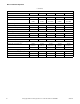
Basic Installation/Operation Electrical Specifications 25 33 35 40 55 75 100 135 165 28 3+PE 6 15 14/2.5 3+N+PE Not available 3+PE Not available 2/3+PE 10 15 14/2.5 3+PE 6 15 14/2.5 3+N+PE Not available 3+PE Not available 2/3+PE 10 15 14/2.5 3+PE 6 15 14/2.5 3+N+PE 18 20 12/4.0 3+PE 18 20 12/4.0 2/3+PE 18 20 12/4.0 3+PE 12 15 14/2.5 3+N+PE Not available 3+PE Not available 2/3+PE 12 15 14/2.5 3+PE 6 15 14/2.5 3+N+PE 18 20 12/4.0 3+PE 18 20 12/4.0 2/3+PE 18 20 12/4.0 3+PE 12 15 14/2.
Basic Installation/Operation Table 3 (continued) Electrical Specifications Standard Phase Wire Full Load Amps Circuit Breaker AWG /mm2 50/60 50/60 50/60 3 3 3 3+PE 3+N+PE 3+PE 19 18 27 25 25 40 10/6.0 10/6.0 8/10.
Basic Installation/Operation Operation Control Identification 3 2 5 1 1 2 3 Keypad Display Emergency Stop Button 4 5 4 Key Switch Serial Port Figure 24 30 © Copyright, Alliance Laundry Systems LLC – DO NOT COPY or TRANSMIT 9001014
Basic Installation/Operation Load the Machine For models: 100PV-200PV 1. Push on the doorlock system to open the door. For models: 18PV-75PV 1. Pull the door handle towards you to open the door. NOTE: Some models may have a door handle with a button that must be pressed. 2. Load the drum to the specified capacity. 3. Close the door by pushing the door handle towards the machine. 2. Load the drum to the specified capacity. 3. Close the door by pushing the door handle towards the machine.
Basic Installation/Operation Disposal of Unit This appliance is marked according to the European directive 2002/96/EC on Waste Electrical and Electronic Equipment (WEEE). This symbol on the product or on its packaging indicates that this product shall not be treated as household waste. Refer to Figure 25. Instead it shall be handed over to the applicable collection point for the recycling of electrical and electronic equipment.