Installation/Operation/Maintenance Drying Tumblers 30 Pound Capacity (28" Wide) 30 Pound Capacity (31.5" Wide) Refer to Page 7 for Model Numbers NOTA: El manual en español aparace después del manual en inglés. KEEP THESE INSTRUCTIONS FOR FUTURE REFERENCE. (If this tumbler changes ownership, be sure this manual accompanies the tumbler.) www.comlaundry.com Part No.
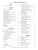
TABLE OF CONTENTS SECTION I Safety Important Safety Instructions . . . . . . . . . . . . . . . . . . 5 SECTION II Introduction Information for Handy Reference . . . . . . . . . . . . . . 7 Parts Ordering Information . . . . . . . . . . . . . . . . . . . 8 Nameplate Location . . . . . . . . . . . . . . . . . . . . . . . . . 8 Roughing-In Dimensions and Specifications Cabinet Dimensions . . . . . . . . . . . . . . . . . . . . . . . . . 9 Roughing-In Dimensions and Specifications Exhaust Thimble Locations . .
SECTION V Operating Instructions SECTION VI Preventive Maintenance Instructions Manual Dual Timer Tumbler . . . . . . . . . . . . . . . . . . 51 Daily . . . . . . . . . . . . . . . . . . . . . . . . . . . . . . . . . . . . . 65 Coin-Operated Tumbler . . . . . . . . . . . . . . . . . . . . . . 52 Lint Removal . . . . . . . . . . . . . . . . . . . . . . . . . . . . 65 Reversing Operation . . . . . . . . . . . . . . . . . . . . . . 53 Monthly . . . . . . . . . . . . . . . . . . . . . . . . . . . . . . .
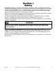
Section I Safety IMPORTANT: Warranty is void unless drying tumbler is installed according to instructions in this manual. Compliance with minimum specifications and requirements detailed herein, and with applicable local gas fitting regulations, municipal building codes, water supply regulations, electrical wiring regulations, and any other relevant statutory regulations.
IMPORTANT: Information must be obtained from your local gas supplier on instructions to be followed if the user smells gas. These instructions must posted in a prominent location. Step-by-step instructions of the safety information below must be posted in a prominent location near the tumbler for customer use. AVERTISSEMENT WARNING FOR YOUR SAFETY, the information in this manual must be followed to minimize the risk of fire or explosion or to prevent property damage, personal injury or death.
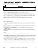
IMPORTANT SAFETY INSTRUCTIONS (SAVE THESE INSTRUCTIONS) WARNING To reduce the risk of fire, electric shock, serious injury or death to persons when using your tumbler, follow these basic precautions: W054 1. Read all instructions before using the tumbler. 2. Refer to the GROUNDING INSTRUCTIONS for the proper grounding of the tumbler. 3.
17. Do not put articles soiled with vegetable or cooking oil in the tumbler, as these oils may not be removed during drying. Due to the remaining oil, the fabric may catch on fire by itself. 18. To reduce the risk of fire, DO NOT put clothes which have traces of any flammable substances such as machine oil, flammable chemicals, thinner, etc. or anything containing wax or chemicals such as in mops and cleaning cloths, or anything dry-cleaned at home with a dry-cleaning solvent in the tumbler. 19.
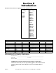
Section II Introduction Information in this manual is applicable to these tumbler models. 30 Pound (28" Wide) JT30XG JT30WE ST30WE ST30WG ST30XG 30 Pound (31.5" Wide) JT30CG STB30CG JTB30CG DTB30CG JT30EG STB30EG JTB30EG DTB30EG JT30CE STB30CE JTB30CE DTB30CE JT30CSH STB30CSH JTB30CSH DTB30CSH JT30CSL STB30CSL JTB30CSL DTB30CSL Conversion Table Multiply By To Obtain Multiply By To Obtain BTU .252 kCal Pounds / sq. in. .06895 Bars BTU 1055 Joules Pounds / sq. in. .070 kg / sq. cm.
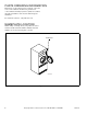
PARTS ORDERING INFORMATION If literature or replacement parts are required, contact the source from whom the machine was purchased or contact Alliance Laundry Systems at (920) 748-3950 for the name and address of the nearest authorized parts distributor. For technical assistance, call (920) 748-3121. NAMEPLATE LOCATION When calling or writing about your product, be sure to mention model and serial numbers. Model and serial numbers are located on nameplate as shown.
ROUGHING-IN DIMENSIONS AND SPECIFICATIONS CABINET DIMENSIONS DEPTH WIDTH OPENING HEIGHT CLEARANCE T326IE3A TUMBLER MODELS OVERALL HEIGHT WIDTH DOOR DEPTH OPENING CLEARANCE 30XG/30WE 72-1/4" (1835 mm) 28" (711 mm) 44-7/8" (1140 mm) 26-3/4" (679 mm) 30-3/4" (781 mm) 30CG/30EG 72-1/4" (1835 mm) 31-1/2" (800 mm) 46-11/16" (1186 mm) 28-1/4" (717 mm) 30-3/4" (781 mm) 30CE/30CSH 72-1/4" (1835 mm) 31-1/2" (800 mm) 44-7/8" (1140 mm) 28-1/4" (717 mm) 30-3/4" (781 mm) 30CSL 72-1/4" (1835
Roughing-In Dimensions and Specifications Exhaust Thimble Locations 30XG and 30WE ACROSS DEPTH ACROSS HEIGHT HEIGHT ACROSS TMB1959N HORIZONTAL EXHAUST TUMBLER MODELS DIAMETER ACROSS VERTICAL EXHAUST HEIGHT DIAMETER ACROSS HEIGHT 30XG/30WE N/A N/A N/A 6" (152 mm) 3-3/8" (86 mm) 3-3/8" (86 mm) 30CG/30CE 30CSL/30CSH 8" (203 mm) 4-7/16" (113 mm) 21-7/8" (556 mm) N/A N/A N/A 30EG 8" (203 mm) 4-7/16" (113 mm) 55-3/8" (1407 mm) N/A N/A N/A 10 © Copyright, Alliance Laundry Syste
Roughing-In Dimensions and Specifications Steam Connection Locations ACROSS SPAN STEAM INLET HEIGHT STEAM OUTLET HEIGHT T328IE3A TUMBLER MODELS 30CSL 30CSH M414545 STEAM INLET DIAMETER 3/4" (19 mm) I.D. ACROSS STEAM OUTLET HEIGHT SPAN DIAMETER 14" (356 mm) 68-3/4" (1746 mm) 7-1/2" (190 mm) 3/4" (19 mm) I.D.
Roughing-In Dimensions and Specifications Gas Connection Locations ACROSS HEIGHT T329IE3A TUMBLER MODELS 12 GAS CONNECTION DIAMETER (N.P.T.) ACROSS HEIGHT 30XG 1/2" (12.7 mm) 12-1/4" (311 mm) 62-1/8" (1578 mm) 30CG/30EG 1/2" (12.
Roughing-In Dimensions and Specifications Electrical Connection Locations ACROSS ACROSS HEIGHT HEIGHT Electric Gas & Steam ELECTRICAL SERVICE - GAS & STEAM MODELS TUMBLER MODELS HEIGHT T330IE3A ELECTRICAL SERVICE - ELECTRIC MODELS ACROSS HEIGHT ACROSS 30XG/30CG/30EG 65" (1651 mm) 3" (76 mm) N/A N/A 30WE N/A N/A 60" (1524 mm) 14" (356 mm) 30CE N/A N/A 60" (1524 mm) 16" (406 mm) 30CSL/30CSH 65" (1651 mm) 3" (76 mm) N/A N/A NOTE: These are approximate dimensions only.
28" wide Gas Tumbler Cabinet Finish: Electrostatically applied thermosetting polyester. Cylinder: 26.5" x 30" (67.3 cm x 76.2 cm) perforated galvanized steel with three baffles Motor: 1/3 H.P., lifetime lubricated, internal overload protected Gas Consumption: 75,000 BTU per hour (79.1 MJ/hr.) Max. Airflow: 370 C.F.M. (175 liters/sec.) Net Weight: 350 Pounds (159 kg) (approximate) 28" wide Electric Tumbler 14 Cabinet Finish: Electrostatically applied thermosetting polyester. Cylinder: 26.
Gas Tumbler Cabinet Finish: Electrostatically applied thermosetting polyester. Cylinder: 30" x 30" (76.2 cm x 76.2 cm) perforated galvanized steel with three baffles; 30 pounds (13.6 kg) dry weight (cotton load) Motor: 1/3 H.P., lifetime lubricated, internal overload protected Energy Saver Models — 80,000 BTU per hour (84.4 MJ/hr.) Gas Consumption: Standard Models — 105,000 BTU per hour (110.8 MJ/hr.) Gas Connection: 1/2 inch N.P.T. Max. Airflow: Energy Saver Models — 250 C.F.M. (118 liters/sec.
Notes 16 © Copyright, Alliance Laundry Systems LLC – DO NOT COPY or TRANSMIT M414545
Section III Installation Instructions RECEIVING INSPECTION Upon delivery, visually inspect crate carton and parts for any visible shipping damage. If the crate, carton or cover are damaged or signs of possible damage are evident, have the carrier note the condition on the shipping papers before the shipping receipt is signed, or advise the carrier of the condition as soon as it is discovered. Remove the crate and protective cover as soon as possible and check the items listed on the packing list.
POSITIONING THE TUMBLER LEVELING THE TUMBLER The tumbler may be removed from the skid before moving it to the installation location or it may be moved while still attached to the skid. To remove tumbler from the skid, unscrew the four shipping capscrews (one at each corner) and remove the tumbler from the skid. The lint panel door will have to be removed in order to remove the two front capscrews. Each tumbler should be leveled within 1/8 inch (3.2 cm) from front to rear, and 1/8 inch (3.
TUMBLER ENCLOSURE CONSTRUCTION IMPORTANT: DO NOT block the airflow at the rear of the tumbler with laundry or other articles. Doing so would prevent adequate air supply to the combustion chamber of the tumbler. WARNING To reduce the risk of serious injury, install lockable door(s) to prevent public access to rear of tumblers. A typical tumbler enclosure is shown in Figure 2. Note that the enclosure touches the tumbler top and side panels. Also, note the minimum and maximum dimensions.
FACILITIES REQUIRED preferred to exhaust tumbler(s) individually to the outdoors. At no point may the cross area of installed venting be less than the cross area of the exhaust thimble of the tumbler. To assure compliance, consult local building code requirements. WARNING A drying tumbler produces combustible lint. To reduce the risk of fire, the tumbler must be exhausted to the outdoors. W057 FLOOR The tumbler must be installed on a level floor capable of supporting 100 pounds per square foot (488.
• Collector Venting While it is preferable to exhaust tumblers individually to the outdoors, a main collector duct may be used if it is sized accordingly. Refer to Figure 5. This illustration indicates minimum diameters, and should be increased if the collector length exceeds 20 feet (6.1 m). The collector duct may be rectangular in cross section, as long as the area is not reduced. Provisions should be made for lint removal and cleaning of the collector duct. The collector duct must be tapered.
WARNING WARNING Solvent gases and vapors from dry cleaning machines create acids when drawn through the heater of a drying tumbler. These acids are corrosive to the drying tumbler as well as to the laundry load being dried. Be sure make-up air is free of solvent gases and vapors.
VERTICAL EXHAUST INSTALLATION HORIZONTAL EXHAUST INSTALLATION WALL CONNECT TO TUMBLER WALL 2" (5.1 cm) MINIMUM EXHAUST OUTLET EXHAUST AIR FLOW MAXIMUM LENGTH OF DUCT 14 FEET (4.3 m) CONNECT TO TUMBLER NO SCREEN OR CAP T030IE3B 2" (5.1 cm) MINIMUM NOTE: WHERE THE EXHAUST DUCT PIERCES A COMBUSTIBLE WALL OR CEILING, AN OPENING HAVING A DIAMETER FOUR INCHES (10.2 cm) LARGER THAN THE DIAMETER OF THE EXHAUST DUCT SHALL BE PROVIDED, AND THE EXHAUST DUCT CENTERED WITHIN THE OPENING.
GAS REQUIREMENTS WARNING To reduce the risk of fire or explosion, DO NOT CONNECT THE GAS LINE TO THE TUMBLER IF THE GAS SERVICE IS NOT THE SAME AS THAT SPECIFIED ON THE TUMBLER SERIAL PLATE! It will first be necessary to convert the gas burner orifice and gas valve. Appropriate conversion kits are available. W060 IMPORTANT: Any product revisions or conversions must be made by the Manufacturer’s Authorized Dealers, Distributors or local service personnel.
WARNING Check all pipe connections, internal and external, for gas leaks using a soapy solution. To reduce the risk of explosion or fire, DO NOT USE AN OPEN FLAME TO CHECK FOR GAS LEAKS! Gas connections should be checked annually for leakage. W063 GAS LINE TO DRYER CONTROLS GAS SUPPLY PIPING SYSTEM GAS “T” FITTING SHUT-OFF VALVE DIRT AND WATER VAPOR TRAP 1/8" (.32 cm) N.P.T. plugged tapping accessible for pressure testing. Gauge connection located upstream from dryer main manual shut-off 6 INCHES (15.
Example of Gas Loop Piping IMPORTANT: Gas loop piping must be installed as illustrated to equalize gas pressure for all tumblers connected to single gas service. Other gas using appliances should be connected upstream from loop. GAS SPACE HEATER MAIN REGULATOR TUMBLERS GAS SHUT-OFF VALVES GAS LINE PRESSURE TAP GAS METER GAS WATER HEATERS ONE INCH (2.54 cm) PIPE GAS LOOP NOTE: Minimum pipe size to tumbler is 1/2" (12.
GAS PIPE SIZE REQUIRED FOR 1,000 BTU NATURAL GAS — .64 SPECIFIC GRAVITY AT 6½ ± 1½ INCH (1.62 ± .37 kPa) WATER COLUMN PRESSURE EQUIVALENT LENGTH GAS APPLIANCES TOTAL BTU/HR. 25 FT. (7.63 m) 50 FT. (15.25 m) 75 FT. (22.88 m) 100 FT. (30.50 m) 125 FT. (38.13 m) 150 FT. (45.75 m) BASED ON 0.3" WATER COLUMN PRESSURE DROP FOR LENGTH GIVEN 1" (2.54cm) 1" (2.54cm) 1" (2.54cm) 1" (2.54cm) 1" (2.54cm) 1" (2.54cm) 1" (2.54cm) 1" (2.54cm) 1" (2.54cm) ¾" (19.05mm) 1" (2.54cm) 1" (2.54cm) 1" (2.
STEAM REQUIREMENTS (Steam Drying Tumblers) The size of the steam service pipe is dependent upon many variables (length, tees, high pressure system, low pressure system, etc.). Specific pipe size information should be obtained from the steam system supplier or a qualified steam fitter. 1. Refer to Figure 9 for proper steam pipe configurations. 2. To prevent condensate draining from headers to tumbler, piping should have a minimum 12 inch rise (30.5 cm) above respective header.
INSTALLING STEAM SOLENOID VALVE AND MAKING STEAM INLET CONNECTIONS INSTALLING STEAM TRAP AND MAKING CONDENSATE RETURN CONNECTIONS High pressure machines require a (constant) 80 to 100 psig (pounds per square inch gauge) (5.62 to 7.03 kg/sq. cm) steam service for optimum operation. Low pressure machines require a (constant) 10 to 15 psig (pounds per square inch gauge) (.70 to 1.05 kg/sq. cm) steam service for optimum operation.
STEAM REQUIREMENTS STEAM DRYING TUMBLERS ONLY NOTE: For sizing of steam lines. Piping must also be sized accordingly for length of runs, and number of elbows. Refer to Table 3. 12" (30.
ELECTRICAL REQUIREMENTS WARNING To reduce the risk of electric shock, fire, explosion, serious injury or death: • • • • • Disconnect electric power to the tumbler before servicing. Close gas shut-off valve to gas tumbler before servicing. Close steam valve to steam tumbler before servicing. Never start the tumbler with any guards/panels removed. Whenever ground wires are removed during servicing, these ground wires must be reconnected to ensure that the tumbler is properly grounded.
The following steps outline the procedure for connecting the electrical service to the tumbler. 3. Check the electrical service phase sequence (three phase only) as follows: a. Energize the electrical service (on reversing tumblers, ensure nonreversing is selected)and momentarily start the tumbler. Check the direction of the cylinder rotation. If the cylinder rotates clockwise (viewed from the front), the phase sequence is correct. If the cylinder rotates counterclockwise, proceed with step “b”.
JUMPER CONFIGURATION INSTRUCTIONS (OPL MICRO CONTROL MODELS ONLY) RING FERRITE INSTALLATION (GAS AND STEAM OPL MICRO CONTROL MODELS ONLY) Changing the transformer configuration jumper is required if any of the following apply: The ring ferrite provided in the information packet must be installed over the power leads during connection of electrical service. The ferrite protects the sensitive electronic controls from destructive electrical disturbances which may be present on power lines to the machine.
ELECTRICAL REQUIREMENTS For 28" wide Tumblers NOTE: Minimum wire sizes are obtained from Canadian Electrical Code and are intended for use as a guideline only. Electrical connections should be made only by a qualified electrical contractor in accordance with all applicable local and national requirements. NOTE: DO NOT use aluminum wire.
ELECTRICAL REQUIREMENTS For 31.5" wide Tumblers NOTE: Minimum wire sizes are obtained from Canadian Electrical Code and are intended for use as a guideline only. Electrical connections should be made only by a qualified electrical contractor in accordance with all applicable local and national requirements. NOTE: DO NOT use aluminum wire.
ACCESSORY TIMING CAM INSTALLATION (Coin Meter Models) The tumbler is shipped with two accessory cams which allow you to change your vending times. The coin slide tumbler accumulator will have a 60 minute timer motor. The accumulator will operate with a two pin cam (30 minutes). The cams furnished with the tumbler will be three pin (20 minutes) and four pin (15 minutes). The 25¢ meter will have a 60 minute timer motor. Refer to Table 8. No.
PRELIMINARY OPERATING CHECKS 1. Remove or open all panels and check accessible bolts, nuts, screws, terminals and fittings for tightness. 2. Check V-belt tension and adjust if necessary. Refer to appropriate paragraphs in Section IV. 3. Steam tumblers: Open the steam service shut-off valves. 4. After performing the previous checks, start the tumbler by pressing START (hold for approximately three seconds). Release the start button and open the cylinder door.
FINAL OPERATING CHECKS OPL MICRO CONTROL TUMBLER Refer to OPL micro-control section to check control for proper operation. MANUAL DUAL TIMER TUMBLER Refer to Figure 13. 1. Set the TEMPERATURE selector to the desired temperature, and set the DRYING and COOLING selectors to maximum. 2. Press the PUSH-TO-START button in and hold it in for approximately three seconds. The motor will start, the heat system will come on and the DRYING indicator will light. 3.
TEMPERATURE SELECTOR DRYING INDICATOR COOLING INDICATOR TEMPERATURE DRYING COOLING HIGH LOW 25 MANUAL DUAL TIMER DURABLE PRESS CONTROL PANEL 10 15 MED 20 30 0 0 15 5 5 10 PUSH TO START T020IE3A PUSH-TO-START BUTTON COOLING TIMER SELECTOR DRYING TIMER SELECTOR Figure 13 RUN INDICATOR TEMPERATURE SELECTOR SINGLE AND DUAL COIN METER COIN SLOT AND KNOB TEMPERATURE *SINGLE COIN-OPERATED DURABLE PRESS CONTROL PANEL PUSH-TO-START BUTTON HIGH COTTON LOW PERMA PRESS MED MIXED PUSH TO START
Notes 40 © Copyright, Alliance Laundry Systems LLC – DO NOT COPY or TRANSMIT M414545
Section IV Adjustments MAIN GAS BURNER AIR SHUTTER All Gas Models NOTICE: Air inlet shutters on the burner must be adjusted so sufficient air is metered into the system for proper combustion and maximum efficiency. Before adjusting the inlet shutters be sure that all lint is removed from lint compartment and lint screen. Air shutter adjustments will vary from location to location and will depend on the vent system, number of units installed, make-up air and line gas pressure.
AIRFLOW SWITCH For Gas and Electric Tumblers The airflow switch (located on the rear of tumbler) is set at the factory for proper operation. Refer to Figure 17. Steam models do not have an airflow switch. However, if there is a problem with the switch, it should be adjusted as follows: NOTICE: Control panel must be in place and access door closed before attempting to adjust airflow switch. IMPORTANT: Airflow switch disc must remain closed during operation.
LOADING DOOR SWITCH The door switch should be adjusted so the cylinder stops when door is opened two inches (5.08 cm), plus or minus 1/4 inch (.63 cm). This switch is a normally open switch and is closed by the interlock rod when the door is closed. If adjustment is required, proceed as follows. Refer to Figure 18. SWITCH ARM ADJUSTING SCREWS DOOR SAFETY SWITCH 1. Close door and start tumbler, slowly open loading door. Cylinder and heat system should shut off when door is open two inches (5.
LOADING DOOR STRIKE The door strike must be adjusted to have sufficient tension to hold loading door closed against force of load tumbling against it. Proper adjustment is when 8 to 15 pounds (35.6 N - 66.7 N) pull is required to open door. If adjustment is required, proceed as follows. Refer to Figure 19. To adjust, open door, loosen jam nut and turn door strike screw in or out as required. Retighten jam nut.
WARNING To reduce the risk of electric shock, fire, explosion, serious injury or death: • • • • • Disconnect electric power to the tumbler before servicing. Close gas shut-off valve to gas tumbler before servicing. Close steam valve to steam tumbler before servicing. Never start the tumbler with any guards/panels removed. Whenever ground wires are removed during servicing, these ground wires must be reconnected to ensure that the tumbler is properly grounded.
BELT DRIVE Reversing Models Refer to Figure 22. Proper tension is when the drive belt can be depressed approximately 1/2 inch (1.27 cm) by applying light thumb pressure (approximately 5 pounds) at a point midway between the sheave and motor pulley. Proper tension is when each cylinder belt can be depressed approximately 3/16 inch (.48 cm) by applying light thumb pressure (approximately 5 pounds) at a point midway between the sheave and the idler. 1. Remove guard from rear of tumbler. 2.
NONREVERSING CHAIN DRIVE MODELS CYLINDER DRIVE CHAIN WA RNING OPER GUARATE ! DO NO DS WITH T IN PL OU ACE.T CYLINDER SPROCKET SHEAVE IDLER SPROCKET JAMNUT ONE HALF INCH (1.27 cm) DEFLECTION DRIVE SPROCKET BELT ADJUSTING BOLT AND NUT IDLER HOUSING GUIDE RAIL ONE HALF INCH (1.27 cm) DEFLECTION GUIDE RAIL WASHER V-BELT MOTOR PULLEY GROUND WIRE (Green) TMB1966N NOTE: Tumbler is shown with guards removed for ilustration purposes only. Never operate the tumbler with the guards removed.
NONREVERSING BELT DRIVE MODELS POLY V-BELT (Poly V-belt is self-adjusting) IDLER HOUSING BOLTS (2) ADJUSTING BOLT IDLER HOUSING ASSEMBLY DRIVE V-BELT T234IE3B Figure 21 48 © Copyright, Alliance Laundry Systems LLC – DO NOT COPY or TRANSMIT M414545
REVERSING MODELS LOCKING BOLT DRIVE BELT ADJUSTING NUT ADJUSTING BOLT (Not Shown) ADJUSTING SCREW CYLINDER BELTS IDLER HOUSING BOLTS (2) IDLER HOUSING ASSEMBLY T322IE3A Figure 22 M414545 © Copyright, Alliance Laundry Systems LLC – DO NOT COPY or TRANSMIT 49
Notes 50 © Copyright, Alliance Laundry Systems LLC – DO NOT COPY or TRANSMIT M414545
Section V Operating Instructions MANUAL DUAL TIMER TUMBLER WARNING To reduce the risk of fire: • DO NOT DRY articles containing foam rubber or similarly textured rubberlike materials. • DO NOT DRY plastics, anything containing wax or chemicals such as mops and cleaning cloths, or anything dry-cleaned at home with a dry-cleaning solvent. • DO NOT TUMBLE fiberglass curtains and draperies unless the label says it can be done.
COIN-OPERATED TUMBLER 1. Energize the electrical circuit to the tumbler at the disconnect switch or the circuit breaker. 2. Open the lint screen panel and check for any accumulated lint on lint screen. Close panel tightly against tumbler frame and lock panel securely. 3. Open the loading door and load the cylinder with laundry. Overloading will result in excessive drying time, wrinkled laundry, and wear to cylinder bearings. 4. Set the TEMPERATURE selector at HIGH (190ºF / 87.
COOLING INDICATOR PUSH-TO-START BUTTON PUSH TO START DRYING INDICATOR COOLING DRYING 50 10 15 40 60 0 0 30 5 20 10 DRYING TIMER SELECTOR COOLING TIMER SELECTOR T216IE3D Figure 23 REVERSING OPERATION This tumbler is equipped with a second motor and additional controls to reverse the direction of the cylinder rotation. The main reason for this option is to prevent tangling of large pieces and minimize wrinkling.
ELECTRONICALLY CONTROLLED OPL TUMBLER INTRODUCTION Drying can be done automatically or by time dry. When drying automatically, the tumbler stops drying when laundry reaches the factory set or programmed dryness level and starts cool down. When time drying, the tumbler stops drying when programmed time ends and starts cool-down. Special Cycle allows user to specify the number of heating cycles and specify temperature from 80°F (27°C) to 180°F (82°C) for all heat cycles.
Figure 25 M414545 © Copyright, Alliance Laundry Systems LLC – DO NOT COPY or TRANSMIT 55
STATUS LIGHTS, SIGNAL AND REVERSING DOOR OPEN DRYING COOL DOWN CUSTOM SIGNAL REVERSING (For Reversing Models only) Lights when door is open. Note: Display window also flashes. Lights when laundry is drying. Lights when laundry is cooling. Lights when a Custom cycle is programmed, recalled or running. When lit, the signal will sound when the laundry is ready for removal. The signal has three loudness levels. These can be set anytime the control is activated.
3. SELECT FABRIC TYPE – Press an ON/SELECT pad to select a temperature. HIGH, MEDIUM, MEDIUM LOW, LOW or NO HEAT for items that should not be dried with heat. A light to the left of the selected pad lights up. AC:** will be displayed when tumbler is in Auto Cool Down. Typical cool down times for fabric selections are preset. Refer to Table 9. The cool down time can only be altered before cycle is started.
B. Time Dry and No Heat After fabric selection, press the TIME pad. Refer to Figure 29. To start the cycle, press START. The total drying time plus cool down time will display. During the cycle, remaining time displays. NO HEAT is a time dry cycle only. When NO HEAT is pressed, a 20 minute preset time will display. This can be changed from 1 minute to 60 minutes by pressing the MORE or LESS pads before pressing START. The COOL DOWN pad does not work in NO HEAT cycles. C.
D. Special Time Mode This mode is just like the Time Dry mode, except that the regulating temperature for each heat cycle ranges from 80°F to 180°F. To enter the Special Time mode, press the SPECIAL TIME pad after selecting a cycle. The display will read “St:**”, where “**” is the drying time. This time can be changed by pressing the MORE or LESS pads. For 1 minute changes, press the pad and release. For 5 minute changes, press the pad and hold. Maximum drying time allowed is 60 minutes.
SECURITY LOCK-OUT SHOW MODE The programming pads can be “locked out” so operators cannot change cycles on their own. When lock-out is used, the operator can use only the factory-set Automatic cycles and the one Custom cycle allowed per Select pad. Before using lock-out, create all desired Custom cycles. This mode will show all LED’s and light up entire display while deactivating all pads. This mode allows loading door to be opened and closed.
M414545 © Copyright, Alliance Laundry Systems LLC – DO NOT COPY or TRANSMIT 61 No Heat Low Medium Low Medium High Select No Heat Low Medium Low Medium High Select Dry Special Dryness Level Cool Down Cool Down Automatic Cool Down Cool Down Special Time Figure 30 Dry Dry Time Temp Temp Custom Cycle Record Load Type Load Type
62 © Copyright, Alliance Laundry Systems LLC – DO NOT COPY or TRANSMIT M414545
M414545 © Copyright, Alliance Laundry Systems LLC – DO NOT COPY or TRANSMIT 63 Load Type Select Figure 31 Dryness Level/Time Cool Down Temperature Drying Instructions Notes
64 © Copyright, Alliance Laundry Systems LLC – DO NOT COPY or TRANSMIT M414545
Section VI Preventive Maintenance Instructions DAILY LINT REMOVAL Refer to Figure 32. 4. The lint screen is designed to completely cover the entire opening in the lint screen hood. Be sure that it does so. Excessive gaps between the lint screen and the lint screen hood allows lint to pass into the ductwork system. WARNING To reduce the risk of serious injury, do not open the lint panel while the tumbler is in operation. Open tumbler door and allow cylinder to completely stop before cleaning lint screen.
MONTHLY BELT TENSION LUBRICATION Check belt tension and adjust if needed. Refer to appropriate section. EVERY SIX MONTHS WARNING To reduce the risk of serious injury or death, disconnect the power to the tumbler before performing this operation. W080 Motor bearings, idler housing bearings and trunnion bearings are pre-lubed sealed bearings and require no lubrication.
THREE MONTH MAINTENANCE (DATES) Clean air vents on drive motor. Check and clean steam coils. (Steam Models Only) Clean exhaust ducts. Check flow of combustion air. Check flow of ventilation air. Check belt tension. Check chain tension. SIX MONTH MAINTENANCE (DATES) Check for loose nuts. Check for loose bolts. Check for loose screws. Check for loose gas connections. Check for loose electrical connections. Check for loose steam connections.
WARNING To reduce the risk of electric shock, fire, explosion, serious injury or death: • • • • • Disconnect electric power to the tumbler before servicing. Close gas shut-off valve to gas tumbler before servicing. Close steam valve to steam tumbler before servicing. Never start the tumbler with any guards/panels removed. Whenever ground wires are removed during servicing, these ground wires must be reconnected to ensure that the tumbler is properly grounded. W002 ENERGY SAVING TIPS SERVICE SAVERS 1.
TROUBLESHOOTING THE TUMBLER 1. Exhaust airflow restriction. Exhaust duct size is recommended to be larger than the exhaust opening. 2. Tumbler inlet air is essential for each unit. Inlet air must be five to seven times the combined areas of the tumbler exhaust outlet. 3. All tumbler panels must be in place and on the machine for proper operation. 4. Gas Models Only: Burner flame improperly adjusted. Adjust the burner air sleeve. 5. Gas Models Only: Gas pressure must be 6 to 8 inches water column (1.49 to 1.
Notes 70 © Copyright, Alliance Laundry Systems LLC – DO NOT COPY or TRANSMIT M414545
Instalación/Operación/Mantenimiento Secadoras Capacidad de 30 libras (28 pulgadas de ancho) Capacidad de 30 libras (31,5 pulgadas de ancho) Consulte página 79 para los números de modelo GUARDE ESTAS INSTRUCCIONES PARA REFERENCIA EN EL FUTURO. (Si esta secadora va a cambiar de dueño, asegúrese de que este manual se entrega con la secadora). www.comlaundry.com Pieza No.
ÍNDICE SECCIÓN I Seguridad Ejemplo de colocación de tubería de gas en bucle . . . . . . . . . . . . . . . . . . . . . . . . . . . . . . . . . . .99 Instrucciones de seguridad importantes . . . . . . . . . . 77 Ejemplo de colocación de tubería de gas de suministro . . . . . . . . . . . . . . . . . . . . . . . . . . . . . . . 99 SECCIÓN II Introducción Información de referencia rápida . . . . . . . . . . . . . . . 79 Información para pedido de piezas . . . . . . . . . . . . . .
Placa de cierre de la puerta de carga . . . . . . . . . . . . .116 Modalidad mostrar . . . . . . . . . . . . . . . . . . . . . . . 132 Accionamiento por cadena modelos sin inversión de giro . . . . . . . . . . . . . . . . . . . . . . . . . . . . . . . . . . . .117 Sensor de temperatura . . . . . . . . . . . . . . . . . . . . 132 Accionamiento por correa modelos sin inversión de giro . . . . . . . . . . . . . . . . . . . . . . . . . . . . . . . . . . . .
Sección I Seguridad IMPORTANTE: La garantía es nula a menos que la secadora se instale según las instrucciones de este manual. Se debe cumplir con las especificaciones y requisitos mínimos aquí detallados, y con todas las regulaciones locales de conexiones de gas correspondientes, códigos de construcción municipales, regulaciones de suministro de agua, regulaciones de conexiones eléctricas, y cualquier otra regulación estatutaria pertinente.
IMPORTANTE: Se debe obtener la información de un proveedor de gas local sobre las instrucciones que deben seguirse si el usuario percibe olor a gas. Estas instrucciones deben colocarse en un lugar a la vista de todos. Las instrucciones paso a paso de la información de seguridad que aparece a continuación debe colocarse a la vista cerca de la secadora para uso del cliente.
INSTRUCCIONES DE SEGURIDAD IMPORTANTES (GUARDE ESTAS INSTRUCCIONES) ADVERTENCIA Para reducir el riesgo de incendio, electrocución y lesiones graves o mortales al usar la secadora, siga las siguientes precauciones básicas: W054SR1 1. Lea las instrucciones antes de utilizar la secadora. 2. Consulte las INSTRUCCIONES DE PUESTA A TIERRA para poner a tierra la secadora de la forma debida. 3.
16. La secadora no funciona con la puerta de carga abierta. NO ponga en derivación el interruptor de seguridad para permitir que la secadora opere con la puerta abierta. La secadora dejará de funcionar cuando se abra la puerta. No utilice la secadora si no deja de funcionar cuando se abra la puerta o si empieza a funcionar sin pulsar o girar el mecanismo de ARRANQUE. Desconecte la secadora y llame a un técnico de servicio. La secadora no funcionará con el panel de pelusa abierto.
Sección II Introducción La información de este manual corresponde a estos modelos de secadora.
INFORMACIÓN PARA PEDIDO DE PIEZAS Si necesita más información escrita o repuestos, póngase en contacto con la tienda donde compró la máquina o con Alliance Laundry Systems, teléfono (920) 748-3950, para obtener el nombre y la dirección del distribuidor de repuestos autorizado más cercano. Para obtener asistencia técnica, llame al (920) 748-3121.
DIMENSIONES Y ESPECIFICACIONES DIMENSIONES DEL ARMARIO PROFUNDIDAD ANCHURA ABERTURA APERTURA ALTURA SEPARACIÓN ESPACIO LIBRE T326IS3A MODELOS DE SECADORA GENERAL ALTURA ANCHURA PUERTA PROFUNDIDAD ABERTURA SEPARACIÓN 30XG/30WE 1835 mm (72-1/4 plg) 711 mm (28 plg) 1140 mm (44-7/8 plg) 679 mm (26-3/4 plg) 781 mm (30-3/4 plg) 30CG/30EG 1835 mm (72-1/4 plg) 800 mm (31-1/2 plg) 1186 mm (46-11/16 plg) 717 mm (28-1/4 plg) 781 mm (30-3/4 plg) 30CE/30CSH 1835 mm (72-1/4 plg) 800 mm (31-1/2 plg)
Dimensiones y especificaciones Ubicación de aberturas de escape 30XG Y 30WE ANCHO ACROSS PROFUNDIDAD DEPTH ANCHO ACROSS ALTURA HEIGHT HEIGHT ALTURA ACROSS ANCHO TMB1959N MODELOS DE SECADORA ESCAPE HORIZONAL DIÁMETRO ANCHO ESCAPE VERTICAL ALTURA 30XG/30WE No disponible No disponible 30CG/30CE 30CSL/30CSH 203 mm (8 plg) 113 mm (4-7/16 plg) 556 mm (21-7/8 plg) 30EG 203 mm (8 plg) 82 No disponible DIÁMETRO ANCHO ALTURA 152 mm (6 plg) 86 mm (3-3/8 plg) 86 mm (3-3/8 plg) No disponible N
Dimensiones y especificaciones Ubicación de conexiones de vapor AL TRAVÉS VANO ALTURA DE LA ENTRADA DE VAPOR ALTURA DE LA SALIDA DE VAPOR T328IS3A MODELOS DE SECADORA 30CSL 30CSH ENTRADA DE VAPOR DIÁMETRO 19 mm (3/4 plg) I.D. M414545 (SP) AL TRAVÉS 356 mm (14 plg) SALIDA DE VAPOR ALTURA VANO DIÁMETRO 1746 mm (68-3/4 plg) 190 mm (7-1/2 plg) 19 mm (3/4 plg) I.D.
Dimensiones y especificaciones Ubicación de conexiones de gas AL TRAVÉS ALTURA T329IS3A MODELOS DE SECADORA 84 CONEXIÓN DE GAS DIÁMETRO (N.P.T.
Dimensiones y especificaciones Ubicación de conexiones eléctricas AL TRAVÉS AL TRAVÉS ALTURA ALTURA Eléctrica Gas y vapor MODELOS DE SECADORA SERVICIO ELÉCTRICO – MODELOS DE GAS Y VAPOR ALTURA AL TRAVÉS T330IS3A SERVICIO ELÉCTRICO – MODELOS ELÉCTRICOS ALTURA AL TRAVÉS 30XG/30CG/30EG 1651 mm (65 plg) 76 mm (3 plg) No disponible No disponible 30WE No disponible No disponible 1524 mm (60 plg) 356 mm (14 plg) 30CE No disponible No disponible 1524 mm (60 plg) 406 mm (16 plg) 30CSL/30CS
Secadora de gas de 28 plg de ancho Acabado del armario: Poliéster termoestable aplicado electrostáticamente. Cilindro: 67,3 cm x 76,2 cm (26,5 plg x 30 plg) acero galvanizado perforado con tres desviadores Motor: 1/3 CV, lubricado de por vida, protegido contra sobrecargas internas Consumo de gas: 79,1 MJ/hora (75.000 BTU por hora) Flujo de aire max.: 175 litros/seg. (370 C.F.M.
Secadora de gas Acabado del armario: Poliéster termoestable aplicado electrostáticamente. Cilindro: 76,2 cm x 76,2 cm (30 plg x 30 plg) acero galvanizado perforado con tres desviadores; 13,6 kg (30 libras) peso en seco (carga de algodón) Motor: 1/3 CV, lubricado de por vida, protegido contra sobrecargas internas Consumo de gas: Modelos con ahorro de energía — 84,4 MJ/hora (80.000 BTU por hora) Modelos estándar — 110,8 MJ/hora (105.000 BTU por hora) Conexión de gas: 1/2 plg N.P.T.
Notas 88 © Copyright, Alliance Laundry Systems LLC – DO NOT COPY or TRANSMIT M414545 (SP)
Sección III Instrucciones de instalación INSPECCIÓN A LA LLEGADA En el momento de la entrega, inspeccione visualmente el embalaje y las piezas para ver si se han producido daños visibles durante el transporte. Si el embalaje o cubierta está dañada o hay signos evidentes de posibles daños, pida al transportista que anote la condición en los papeles de transporte antes de firmar el recibo de envío, o comunique al transportista la condición tan pronto como la descubra.
UBICACIÓN DE LA SECADORA NIVELACIÓN DE LA SECADORA La secadora puede retirarse del calzo antes de desplazarla a la ubicación de instalación, o puede desplazarse cuando aun está acoplada al mismo. Para retirar la secadora del calzo, destornille los cuatro pernos de sombrerete de envío (uno en cada esquina) y retire la secadora del calzo. La puerta del panel de pelusa tendrá que desmontarse para poder retirar los dos pernos delanteros.
CONSTRUCCIÓN DEL RECINTO DE LA SECADORA IMPORTANTE: NO bloquee el paso de aire por la parte trasera de la secadora con ropa u otros artículos. Al hacer esto se impide el suministro de aire adecuado a la cámara de combustión de la secadora. En la Figura 2 se muestra un recinto típico de secadora. Observe que el recinto hace contacto con los paneles superior y laterales de la secadora. Observe también las dimensiones mínima y máxima.
INSTALACIONES REQUERIDAS Consulte los requisitos de los códigos de construcción locales para cerciorarse de que se cumpla con los mismos. ADVERTENCIA conducto de escape centrado en la abertura. Cuando los conductos atraviesen paredes, techos, pisos o tabiques, el espacio alrededor del conducto debe estar sellado con material que no sea combustible. Consulte las Figuras 3, 4 y 5. • Ventilación individual Las secadoras producen pelusas combustibles.
• Conducto colector de ventilación Aunque se prefiere descargar el escape de las secadoras individualmente al exterior, se puede usar un conducto colector principal si tiene las dimensiones apropiadas. Consulte la Figura 5. Esta ilustración indica diámetros mínimos, y debe aumentarse si la longitud del conducto colector es mayor que 6,1 m (20 pies). La sección transversal del conducto colector puede ser rectangular o cuadrada, siempre y cuando no se reduzca el área.
ADVERTENCIA ADVERTENCIA De los gases y vapores de los disolventes de las máquinas de limpieza en seco emanan ácidos durante su paso por el calentador del tambor secador. Estos ácidos tienen efectos corrosivos sobre el tambor secador y sobre la carga en proceso de secado. Asegúrese de que el aire de reposición esté libre de gases y vapores de disolventes.
PARA UN MEJOR RENDIMIENTO Proveer un conducto de escape individual por cada secadora de tambor. No instalar calentador de agua en salas donde haya secadoras. Es mejor tener el calentador de agua en sala separada, con su entrada de aire separada. NOTA: No instalar ninguna tela metálica o malla en esta abertura, pues se acumularían pelusas y se afectaría la correcta descarga de aire de las secadoras.
INSTALACIÓN DEL ESCAPE VERTICAL INSTALACIÓN DEL ESCAPE HORIZONTAL PARED 51 mm (2 PLG) MÍNIMO CONECTE A LA SECADORA SIN MALLA NI TAPÓN SALIDA DE ESCAPE FLUJO DE AIRE DEL ESCAPE LONGITUD MÁXIMA DEL DUCTO: 4,3 m (14 PIES) PARED CONECTE A LA SECADORA SIN MALLA NI TAPÓN NOTA: DONDE EL DUCTO DE ESCAPE ATRAVIESE UNA PARED DE MATERIAL COMBUSTIBLE O UN CIELO RASO, DEBERÁ HACERSE UN AGUJERO DE UN DIÁMETRO 102 mm (4 PLG) MAYOR QUE EL DIAMETRO DEL DUCTO DE ESCAPE, Y MANTENERSE EL DUCTO CENTRADO EN EL AGUJERO.
REQUISITOS DE GAS ADVERTENCIA Para reducir el riesgo de incendio o explosión, ¡NO CONECTE LA LÍNEA DE GAS A LA SECADORA SI EL SERVICIO DE GAS NO CORRESPONDE A LO ESPECIFICADO EN LA PLACA DEL NÚMERO DE SERIE DE LA SECADORA! Primero habrá que efectuar la conversión necesaria del quemador de gas y de la válvula de gas. Se dispone de juegos de materiales para efectuar dicha conversión.
ADVERTENCIA Inspeccione todas las conexiones de la tubería, internas y externas, mediante una solución jabonosa, a fin de detectar eventuales fugas de gas. Para reducir el riesgo de explosión o fuego, ¡NO EMPLEE NUNCA UNA LLAMA ABIERTA AL BUSCAR LAS FUGAS DE GAS! Esta inspección tiene que efectuarse cada 12 meses.
Ejemplo de colocación de tubería de gas en bucle IMPORTANTE: La tubería del bucle de gas deberá ser instalada como se ilustra para ecualizar la presión de gas de todas las secadoras conectadas una única línea de suministro de gas. Las demás máquinas que funcionen con gas deberán ser conectadas antes del bucle.
TAMAÑO DE TUBO DE GAS REQUERIDO PARA GAS NATURAL DE 1.000 BTU – PESO ESPECÍFICO DE 0,64 A 1,62 ± 0,37 kPa (6½ ± 1½ PULGADAS) DE COLUMNA DE AGUA DE PRESIÓN LONGITUD EQUIVALENTE TOTAL DE APARATOS DE GAS BTU/ HORA 25 PIES (7,63 m) 50 PIES (15,25 m) 75 PIES (22,88 m) 100 PIES (30,50 m) 125 PIES (38,13 m) 150 PIES (45,75 m) BASADO EN UNA CAÍDA DE PRESIÓN DE 0,3 PULGADAS DE COLUMNA DE AGUA POR LA LONGITUD DADA 100.
REQUISITOS DE VAPOR (Secadoras de vapor) El tamaño de la tubería de servicio de vapor depende de muchas variables (longitud, uniones en T, sistema de alta presión, sistema de baja presión, etc.). Obtenga los tamaños del tubo de servicio de vapor específicos del proveedor del sistema de vapor o de un técnico de vapor cualificado. 1. Consulte en la Figura 9 las configuraciones apropiadas para tubos de vapor. 2.
INSTALACIÓN DE LA VÁLVULA DE SOLENOIDE DE VAPOR Y CONEXIONES DE ENTRADA DE VAPOR Las máquinas de alta presión requieren un servicio de vapor (constante) de 5,62 a 7,03 kg/cm2 (80 a 100 psig) para una operación óptima. Las máquinas de baja presión requieren un servicio de vapor (constante) de 0,70 a 1,05 kg/cm2 (10 a 15 psig) para una operación óptima. Los pasos siguientes describen el procedimiento para la instalación de la válvula de solenoide de vapor y la conexión del servicio de vapor. a.
REQUISITOS DE VAPOR SECADORAS DE VAPOR SOLAMENTE NOTA: Para las dimensiones de las tuberías de vapor. La tubería debe dimensionarse según la longitud de los tramos y el número de codos. Consulte la Tabla 3.
REQUISITOS ELÉCTRICOS ADVERTENCIA Para reducir el riesgo de electrocución, incendio, explosión, lesiones graves o mortales: • Desconecte la corriente eléctrica de la secadora antes de efectuar el servicio de la misma. • Cierre la válvula de cierre de gas de la secadora antes de efectuar el servicio de la misma. • Cierre la válvula de paso directo de vapor de la secadora antes de efectuar el servicio de la misma. • No ponga nunca en marcha la secadora cuando esté desprovista de sus protectores y paneles.
Los pasos siguientes describen el procedimiento para conectar el servicio eléctrico a la secadora. NOTA: El diagrama de conexiones se suministra en el paquete de materiales del cilindro. 3. Compruebe la secuencia de fases de servicio eléctrico (trifásico solamente) de la manera siguiente: a. Active el servicio eléctrico (en las secadoras con inversión de giro, asegure que se seleccione sin inversión de giro) y arranque la secadora. Compruebe el sentido de giro del cilindro.
INSTRUCCIONES DE CONFIGURACIÓN DEL PUENTE (MODELOS OPL MICRO CONTROL SOLAMENTE) INSTALACIÓN DEL ANILLO DE FERRITA (MODELOS OPL MICRO CONTROL DE GAS Y VAPOR SOLAMENTE) Se requiere cambiar el puente de configuración del transformador si se da alguno de los siguientes aspectos: El anillo de ferrita proporcionado en el paquete de información debe instalarse sobre los cables de corriente durante la conexión del servicio eléctrico.
REQUISITOS ELÉCTRICOS Para secadoras de 28 pulgadas de ancho NOTA: Los tamaños mínimos de los cables se obtienen del Canadian Electrical Code y se deben utilizar sólo como guía. Solamente un contratista eléctrico cualificado debe efectuar las conexiones eléctricas según todos los requisitos locales y nacionales correspondientes. NOTA: NO UTILICE cable de aluminio.
REQUISITOS ELÉCTRICOS Para secadoras de 31,5 pulgadas de ancho NOTA: Los tamaños mínimos de los cables se obtienen del Canadian Electrical Code y se deben utilizar sólo como guía. Solamente un contratista eléctrico cualificado debe efectuar las conexiones eléctricas según todos los requisitos locales y nacionales correspondientes. NOTA: NO UTILICE cable de aluminio.
INSTALACIÓN DE LEVA DE SINCRONIZACIÓN ACCESORIA (modelos con medidor de monedas) La secadora se envía con dos levas accesorias que le permiten cambiar sus tiempos de venta. El acumulador de la deslizadora de monedas de la secadora tendrá un motor de temporizador de 60 minutos. El acumulador funcionará con una leva de dos pasadores (30 minutos). Las levas que incorporadas con la secadora serán de tres pasadores (20 minutos) y cuatro pasadores (15 minutos).
COMPROBACIONES DE OPERACIÓN PRELIMINARES 1. Quite o abra todos los paneles y compruebe que estén apretados todos los pernos, tuercas, tornillos, terminales y conexiones. 2. Compruebe la tensión de la correa y ajústela si es necesario. Consulte los párrafos correspondientes en la Sección IV. 3. Secadoras de vapor: Abra las válvulas de cierre de servicio de vapor. 4. Después de realizar las comprobaciones anteriores, ponga en marcha la secadora pulsando START (Arranque).
COMPROBACIONES DE OPERACIÓN FINALES SECADORA CON OPL MICRO CONTROL SECADORA OPERADA CON MONEDAS Consulte la sección de OPL micro control para comprobar que el control está funcionando correctamente. Consulte la Figura 14. SECADORA DE TEMPORIZADOR DUAL MANUAL Consulte la Figura 13. 1. Ponga el selector TEMPERATURE (temperatura) a la temperatura deseada. 2. Inserte el número requerido de monedas en la ranura, gire la perilla por completo en el sentido de las agujas del reloj y suéltelo.
SELECTOR DE TEMPERATURA INDICADOR DE SECADO INDICADOR DE ENFRIAMIENTO TEMPERATURE DRYING COOLING HIGH LOW 25 REGULADOR DE TIEMPO MANUAL DOBLE PANEL DE CONTROL DE PLANCHADO PERMANENTE 10 15 MED 20 30 0 0 15 5 5 10 PUSH TO START T020IS3A BOTÓN PULSADOR DE ARRANQUE SELECTOR DEL SELECTOR DEL REGULADOR DE TIEMPO REGULADOR DE DE ENFRIAMIENTO TIEMPO DE SECADO Figura 13 INDICADOR DE MARCHA SELECTOR DE TEMPERATURA BOTÓN Y RANURA DE MONEDA DE CONTADOR DE MONEDA SIMPLE Y DOBLE TEMPERATURE *PANEL
Sección IV Ajustes OBTURADOR PRINCIPAL DE AIRE DEL QUEMADOR DE GAS Todos los modelos de gas AVISO: Los obturadores de la entrada de aire en el quemador debe ajustarse de modo que se mida un aire suficiente en el sistema para una combustión apropiada y una máxima eficiencia. Antes de ajustar los obturadores de entrada, asegúrese de quitar toda la pelusa del compartimento y la rejilla de pelusa.
INTERRUPTOR DE FLUJO DE AIRE Para secadoras de gas y eléctricas El interruptor de flujo de aire (ubicado en la parte trasera de la secadora) está fijado de fábrica para la operación adecuada. Consulte la Figura 17. Los modelos de vapor no tienen un interruptor de flujo de aire. Sin embargo, si hay un problema en el interruptor, debe ajustarse de la forma siguiente: AVISO: El panel de control debe estar colocado y la puerta de acceso cerrada antes de tratar de ajustar el interruptor de flujo de aire.
INTERRUPTOR DE LA PUERTA DE CARGA El interruptor de la puerta deberá ajustarse de forma que el cilindro se detenga cuando la puerta se abra 5,08 cm (2 pulgadas), con una tolerancia de ± 0,63 cm (1/4 de pulgada). El interruptor es normalmente un interruptor abierto y se cierra por medio de la varilla de bloqueo al cerrarse la puerta. Si se requiere ajuste, proceda de la siguiente manera. Consulte la Figura 18. BRAZO DE INTERRUPTOR TORNILLOS DE AJUSTE INTERRUPTOR DE SEGURIDAD DE PUERTA 1.
PLACA DE CIERRE DE LA PUERTA DE CARGA La placa de cierre de la puerta debe ajustarse para que tenga una tensión suficiente para mantener la puerta cerrada contra la fuerza de la carga agitada contra ésta. Los ajustes son apropiados cuando se requiere una fuerza de 35,6 a 66,7 N (8 a 15 libras) para abrir la puerta. Si se requiere ajuste, proceda de la siguiente manera. Consulte la Figura 19.
ADVERTENCIA Para reducir el riesgo de electrocución, incendio, explosión, lesiones graves o mortales: • Desconecte la corriente eléctrica de la secadora antes de efectuar el servicio de la misma. • Cierre la válvula de cierre de gas de la secadora antes de efectuar el servicio de la misma. • Cierre la válvula de paso directo de vapor de la secadora antes de efectuar el servicio de la misma. • No ponga nunca en marcha la secadora cuando esté desprovista de sus protectores y paneles.
ACCIONAMIENTO POR CORREA Modelos con inversión de giro Consulte la Figura 22. La correa está bien tensada cuando se puede combar 1,27 cm (1/2 pulgada) ejerciendo una ligera presión (aproximadamente 5 libras) con el dedo pulgar en el punto medio entre la roldana y la polea del motor. La correa está bien tensada cuando se puede combar aproximadamente 0,48 cm (3/16 de pulgada) ejerciendo una ligera presión (aproximadamente 5 libras) con el dedo pulgar en el punto medio entre la roldana y la polea del motor. 1.
SIN INVERSIÓN DE GIRO MODELOS DE ACCIONAMIENTO POR CADENA CADENA DE ACCIONAMIENTO DEL CILINDRO WA RNING OPER GUARATE ! DO NO DS WITH T IN PL OU ACE.
SIN INVERSIÓN DE GIRO MODELOS DE ACCIONAMIENTO POR CORREA CORREA EN “V” DE POLIETILENO (la correa en “V” de polietileno es autoajustable) PERNOS DEL ALOJAMIENTO DE LA TRANSMISIÓN (2) CONJUNTO DEL ALOJAMIENTO DE LA TRANSMISIÓN PERNO DE AJUSTE CORREA EN “V” DE TRANSMISIÓN T234IS3B Figura 21 120 © Copyright, Alliance Laundry Systems LLC – DO NOT COPY or TRANSMIT M414545 (SP)
MODELOS CON INVERSIÓN DE GIRO PERNO DE INMOVILIZACIÓN CORREA DE ACCIONAMIENTO TUERCA DE AJUSTE PERNO DE AJUSTE (no ilustrado) TORNILLO DE AJUSTE CORREAS DEL CILINDRO IPERNOS DEL ALOJAMIENTO DE LA POLEA LOCA (2) CONJUNTO DE ALOJAMIENTO DE LA POLEA LOCA T322IS3A Figura 22 M414545 (SP) © Copyright, Alliance Laundry Systems LLC – DO NOT COPY or TRANSMIT 121
Notas 122 © Copyright, Alliance Laundry Systems LLC – DO NOT COPY or TRANSMIT M414545 (SP)
Sección V Instrucciones de operación ADVERTENCIA Para reducir el riesgo de incendio: • NO SEQUE artículos que contengan caucho de espuma o materiales con textura semejantes al caucho. • NO SEQUE plásticos, artículos que contengan cera o productos químicos tales como fregonas y trapos de limpieza, o cualquier artículo lavado en seco con un disolvente de tintorería. • NO AGITE cortinas ni tapicerías de fibra de vidrio a menos que la etiqueta diga que puede hacerse.
SECADORA OPERADA CON MONEDAS 1. Active el circuito eléctrico que va a la secadora en el interruptor de desconexión o el cortacircuitos. 2. Abra el panel de la rejilla de pelusa y compruebe si hay pelusa acumulada en la rejilla. Cierre bien el panel contra el bastidor de la secadora y bloquéelo. 3. Abra la puerta de carga y cargue la colada en el cilindro. Si se sobrecarga se podría dar un tiempo de secado excesivo, una colada con arrugas y el desgaste de los rodamientos del cilindro. 4.
INDICADOR DE SECADO INDICADOR DE ENFRIAMIENTO PUSH TO START COOLING DRYING 50 10 15 40 60 0 0 30 5 BOTÓN PULSADOR DE ARRANQUE 20 10 SELECTOR DE TIEMPO DE SECADO SELECTOR DE TIEMPO DE ENFRIAMIENTO T216IS3A Figura 23 OPERACIÓN DE INVERSIÓN DE GIRO Esta secadora está equipada con un segundo motor y controles adicionales que invierten el sentido del giro del cilindro. La razón principal que da esta opción es prevenir el enredo de las piezas de ropa de gran tamaño y reducir las arrugas.
SECADORA OPL CONTROLADA ELECTRÓNICAMENTE INTRODUCCIÓN El secado puede hacerse automáticamente o por tiempo de secado. Al secar automáticamente, la secadora deja de secar cuando la colada alcanza el nivel de secado de fábrica o programado y empieza a enfriarse. Durante el tiempo de secado, la secadora deja de secar cuando transcurre el tiempo programado y empieza el enfriamiento.
Figura 25 M414545 (SP) © Copyright, Alliance Laundry Systems LLC – DO NOT COPY or TRANSMIT 127
LUCES DE ESTADO, SEÑAL E INVERSIÓN DE GIRO DOOR OPEN (puerta abierta) Se enciende cuando se abre la puerta. Nota: La ventana de visualización también destella. DRYING (secado) Se enciende cuando se está secando la colada. COOL DOWN (enfriamiento) Se enciende cuando se está enfriando la colada. CUSTOM (a la medida) Se enciende cuando se programa, llama o ejecuta un ciclo personal. SIGNAL (señal) Cuando se enciende, la señal sonará cuando la colada esté lista para sacarse.
Se mostrará “AC:**” cuando la secadora esté en Auto Cool Down (enfriamiento automático). Los tiempos típicos de enfriamiento para el tipo de tela están prefijados. Consulte la Tabla 9. El tiempo de enfriamiento sólo puede alterarse antes de que empiece el ciclo. Para alterar el tiempo de enfriamiento, pulse el botón COOL DOWN (enfriamiento) y después pulse MORE (más) o LESS (menos) (cuando se altere el tiempo de enfriamiento, aparecerá TC:**). Para cambios de 1 minuto, pulse y suelte el botón.
B. Secado por tiempo y Sin calor Después de seleccionar el tejido, pulse el botón TIME (tiempo). Consulte la Figura 29. Pulse START (Arrancar) para empezar el ciclo. Se mostrarán el tiempo de secado total más el tiempo de enfriamiento. Durante el ciclo se muestra el tiempo que queda. NO HEAT (sin calor) es un ciclo de tiempo de secado solamente. Cuando se pulsa NO HEAT (sin calor), se mostrará un tiempo prefijado de 20 minutos.
D. Modalidad de tiempo especial Esta modalidad es como la modalidad Time Dry (secado por tiempo), excepto que la temperatura reguladora para cada ciclo de calor oscila entre 27°C (80°F) a 82°C (180°F). Para entrar en la modalidad Special Time (Tiempo especial), pulse el botón SPECIAL TIME después de haber seleccionado un ciclo. La pantalla mostrará “St:**”, siendo “**” el tiempo de secado. Este tiempo puede cambiarse pulsando el botón MORE (más) o el botón LESS (menos).
BLOQUEO DE SEGURIDAD Los botones de programación pueden “bloquearse” de modo que los operadores no puedan cambiar los ciclos por su cuenta. Cuando se use el bloqueo, el operador puede usar sólo los ciclos automáticos fijados de fábrica y el ciclo a la medida permitido por botón Select (seleccionar). Antes de usar el bloqueo, cree todos los ciclos a la medida deseados. Para bloquear, mantenga pulsado el botón SIGNAL (señal) y pulse MORE (más) en la modalidad en vacío.
MODALIDAD MOSTRAR Esta modalidad mostrará los LED y encenderá toda la pantalla mientras se desactivan todos los botones. Esta modalidad permite abrir y cerrar la puerta de carga. Para entrar en esta modalidad, el control debe estar primero en la modalidad de vacío. Mantenga pulsado el botón START (Arranque) y pulse el botón SAVE CUSTOM (Guardar a la medida). Para salir de la modalidad de mostrar, mantenga pulsado el botón START (Arranque) y pulse el botón SAVE CUSTOM (Guardar a la medida).
134 © Copyright, Alliance Laundry Systems LLC – DO NOT COPY or TRANSMIT M414545 (SP) Sin calor Baja Media-Baja Media Alta Seleccionar Sin calor Baja Media-Baja Media Alta Seleccionar Secado Nivel de secado Enfriamiento Especial Enfriamiento Automático Figura 30 Enfriamiento Secado Enfriamiento Tiempo especial Secado Tiempo Temperatura Temperatura Registro de ciclos a la medida Tipo de carga Tipo de carga
M414545 (SP) © Copyright, Alliance Laundry Systems LLC – DO NOT COPY or TRANSMIT 135 Tipo de carga Seleccionar Figura 31 Nivel de secado/Tiempo Enfriamiento Temperatura Instrucciones de secado Notas
136 © Copyright, Alliance Laundry Systems LLC – DO NOT COPY or TRANSMIT M414545 (SP)
Sección VI Instrucciones de mantenimiento preventivo DIARIAMENTE REMOCIÓN DE PELUSA Consulte la Figura 32. 4. La rejilla de la pelusa está diseñada para tapar completamente la abertura en la cubierta de la rejilla de la pelusa. Asegúrese de que así sea. Las separaciones excesivas entre la rejilla de la pelusa y la cubierta de la rejilla de la pelusa permiten el paso de ésta al sistema de conductos.
MENSUALMENTE 4. Inspeccione el área del secador para asegurarse de que no haya nada que obstruya el paso del aire de combustión y ventilación. LUBRICACIÓN 5. Quite el panel delantero y limpie la pelusa acumulada. ADVERTENCIA TENSIÓN DE LA CORREA Para reducir el riesgo de lesiones graves y de muerte, desconectar la secadora de la corriente antes de ejecutar estos pasos de mantenimiento.
MANTENIMIENTO DE TRES MESES (FECHAS) Limpie los respiraderos del motor de impulsión. Compruebe y limpie los serpentines de vapor. (modelos de vapor solamente) Limpie los conductos de escape. Compruebe el flujo de aire de combustión. Compruebe el flujo del aire de ventilación. Compruebe la tensión de la correa. Compruebe la tensión de la cadena. MANTENIMIENTO DE SEIS MESES (FECHAS) Compruebe si hay tuercas sueltas. Compruebe si hay pernos sueltos. Compruebe si hay tornillos sueltos.
ADVERTENCIA Para reducir el riesgo de electrocución, incendio, explosión, lesiones graves o mortales: • Desconecte la corriente eléctrica de la secadora antes de efectuar el servicio de la misma. • Cierre la válvula de cierre de gas de la secadora antes de efectuar el servicio de la misma. • Cierre la válvula de paso directo de vapor de la secadora antes de efectuar el servicio de la misma. • No ponga nunca en marcha la secadora cuando esté desprovista de sus protectores y paneles.
RESOLUCIÓN DE PROBLEMAS DE LA SECADORA 1. Restricción del flujo de aire de escape. Se recomienda que el tamaño de conducto de escape sea más grande que la abertura de escape. 2. La entrada de aire a la secadora es esencial para todas las unidades. El área de la entrada de aire deberá ser cinco a siete veces mayor que las áreas combinadas de la salida de escape de la secadora. 3. Todos los paneles de la secadora deberán estar en su lugar en la máquina para una operación apropiada. 4.
Notas 142 © Copyright, Alliance Laundry Systems LLC – DO NOT COPY or TRANSMIT M414545 (SP)