
Installation manual


© Copyright, Alliance Laundry Systems LLC – DO NOT COPY or TRANSMIT
Installation
802702
24
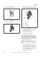
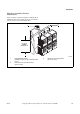
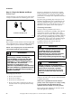
Figure 21
Figure 22
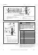
A Backdraft Damper, Part No. 58786 (obtain locally),
should be installed in a 4 inch (10.2 cm) diameter
VERTICAL duct system. This will prevent a backdraft
when dryer is not in use, and will keep the exhaust air
in balance within the central exhaust system.
H318I
1 NOTE: Where the exhaust duct pierces a
combustible wall or ceiling, the opening must be
sized per local codes.
3 2 in. (5 cm) Minimum or Clearance per Local
Codes
4 No Screen or Cap
2 Wall 5 Clean Out Cover
– Inspect Monthly
2
3
4
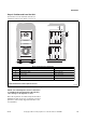
EXHAUST
OUTLET
KJIHGFEDCBA
5
30°
1
EXHAUST AIR FLOW
MAXIMUM LENGTH OF DUCT
30 feet (9.1 m)
HORIZONTAL EXHAUST INSTALLATION
AIR
FLOW
H319I
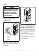
1 Roof
2 No Screen or Cap
3 Wall
4 2 in. (5 cm) Minimum or Clearance Per Local
Codes
5 NOTE: Where the exhaust duct pierces a
combustible wall or ceiling, an opening must
be sized as shown or per local codes.
3
1
4
5
CONNECT TO DRYER
VERTICAL EXHAUST INSTALLATION
2
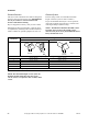
Duct Station
Minimum Diameter of
Collector Duct
A4 inches (10.2 cm)
B8 inches (20.3 cm)
C9 inches (22.9 cm)
D10 inches (25.4 cm)
E11 inches (27.9 cm)
F12 inches (30.5 cm)
G13 inches (32.6 cm)
H14 inches (35.6 cm)
I15 inches (38.1 cm)
J15 inches (38.1 cm)
K16 inches (40.6 cm)
To reduce the risk of fire and the
accumulation of combustion gases, DO NOT
exhaust dryer air into a window well, gas
vent, chimney or enclosed, unventilated
area, such as an attic, wall, ceiling, crawl
space under a building or concealed space
of a building.
W045
WARNING