Operation/Maintenance Washer-Extractors Cabinet Hardmount S, P, and V-Series Microcomputers Coin and Non-Coin Models Refer to Page 3 for Model Identification NOTA: El manual en español aparece después del manual en inglés. CHM166C Keep These Instructions for Future Reference. (If this machine changes ownership, this manual must accompany machine.) www.comlaundry.com Part No.
Table of Contents Introduction......................................................................................... Model Identification ............................................................................. Nameplate Location.............................................................................. Replacement Parts ................................................................................ Customer Service................................................................................
Notes 2 © Copyright, Alliance Laundry Systems LLC – DO NOT COPY or TRANSMIT F232137
Introduction Model Identification Information in this manual is applicable to these models: HC18SN2 HC27VX2 HC50SN2 SC35VN2 UC20PN2 UC40VN2 HC18VC2 HC30SN2 HC50VC2 SC35VNV UC20VN2 UC40VNV HC18VX2 HC30VC2 HC50VX2 SC40VN2 UC27PN2 UC50PN2 HC20SN2 HC30VX2 HC80VCV SC40VNV UC27VN2 UC50VN2 HC20VC2 HC35SN2 HC80VNV SC50VN2 UC30PN2 UC50VNV HC20VX2 HC35VC2 HC80VXV SC50VNV UC30VN2 UC80VNV HC25VC2 HC35VX2 SC18VN2 SC80VNV UC35PN2 UC125VNV HC25VX2 HC40SN2 SC20VN2 SC125VNV UC35
Introduction Nameplate Location Replacement Parts The nameplate is located at the rear of the machine and inside door. Always provide the machine’s serial number and model number when ordering parts or when seeking technical assistance. If literature or replacement parts are required, contact the source from whom the machine was purchased or contact Alliance Laundry Systems at (920) 748-3950 for the name and address of the nearest authorized parts distributor.
Safety Information Precautionary statements (“DANGER”, “WARNING” and “CAUTION”), followed by specific instructions, are found in this manual and on machine decals. These precautions are intended for the personal safety of the operator, user, servicer and those maintaining the machine. DANGER DANGER indicates the presence of a hazard that will cause severe personal injury, death, or substantial property damage if the danger is ignored.
Safety Information 9. Do not install or store the washer where it will be exposed to water and/or weather. 10. Do not tamper with the controls. 11. Do not repair or replace any part of the washer, or attempt any servicing unless specifically recommended in the user-maintenance instructions or in published user-repair instructions that the user understands and has the skills to carry out. 12.
Operation Control Panel The Up and Down keys are used in cycle selection. Press these keys to move among cycles from smaller to greater, or greater to smaller. Figure 2 shows the control panel for S, P and V-computer machines. 2 The Start The Stop key is not active in normal Run Mode. In Run Mode it is used only for stopping test cycle. 3 4 1 The LED display informs operator of various functions throughout operation of machine. Refer to tables on the following pages for displays and their meanings.
Operation Display Indications Table 1 through Table 4 list the various displays and what they mean. The operator should become familiar with these computer displays. Display Indications for S-Series – Non-Coin Display Meaning Display Meaning S-05 Program identification code (ROM) (this is an example only) bFIL Warm fill (both hot and cold) HoLd Wait...
Operation Display Indications for V-Series – Coin Display FC 5 Meaning Display Meaning Program identification code (ROM) (this is an example only) HFIL Hot fill Lo Low water level Wait...
Operation Display Indications for V-Series – Non-Coin Display Meaning Display Meaning Program identification code (ROM) (this is an example only) nEd Medium water level HI High water level HoLd Wait...
Operation Display Indications for V-Series Two Speed – Non-Coin Display F23n Meaning Display Meaning Program identification code (ROM) (this is an example only) FIL6 Sixth fill (8th of 11 segments) FIL7 Seventh fill (9th of 11 segments) HoLd Wait...
Operation Operating Instructions 1. Turn on main power source (circuit breaker). 3. Load to capacity whenever possible. DO NOT OVERLOAD. Refer to Figure 5. For non-coin models: Turn on the On/Off switch on the front panel to the On position. 2. Push button and turn handle clockwise to open. Refer to Figure 3. U003I Figure 5 4. Close door and turn handle counterclockwise until button pops out. Refer to Figure 6.
Operation 5. Add liquid and/or powder supplies to supply dispenser. Refer to Figure 7. a. Add detergent to container 1. 9. When applicable, add bleach to container 2 when the display reads “bLCH”. Refer to Figure 9. b. Add softener to container 3. For non-coin models: Liquid supplies may be injected directly into the supply dispenser by an external chemical supply dispenser. Refer to Installation and Programming Manuals. 6. Press the Up or Down key to select wash cycle. Press the Start key.
Notes 14 © Copyright, Alliance Laundry Systems LLC – DO NOT COPY or TRANSMIT F232137
Maintenance 4. Check door interlock before starting operation: WARNING Sharp Edges. Can cause personal injury. Wear safety glasses and gloves, use proper tools and provide lighting when handling sheet metal parts. W366 IMPORTANT: Replace all panels that are removed to perform service and maintenance procedures. Do not operate the machine with missing guards or with broken or missing parts. Do not bypass any safety devices. Daily a. Attempt to start the machine with the door open.
Maintenance Weekly Monthly 1. For variable-speed models only, clean the AC drive box filter(s) weekly or more frequently as needed: NOTE: If fan filter service indicator light is on, fan filter must be cleaned immediately to prevent possible damage. Press thermostat button to reset indicator light. a. Open the top cover. b. Grasp the filter handle and pull straight up to remove filter. c. Wash the filter with warm water and allow filter to air-dry. As an alternative, the filter may be vacuumed clean.
Maintenance c. For flat-pulley drive systems, verify allowable distance of belt from edge of pulley as shown in Table 5 below: Flat-Pulley Alignment Model Allowable Distance from Edge 18 – 40 3/32 in. (2 mm) 50 3/8 in. (10 mm) 1 2 Table 5 d. For variable-speed models only, verify that V-belts are properly tensioned by applying a set force to the belt and measuring the deflection to determine the belt tension. Refer to Table 6 for the acceptable belt tension ranges.
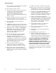
Maintenance 1 2 H047I H047I 1 2 Bearing Grease Fitting Seal Grease Fitting Figure 12 2. For 80 pound capacity models only, lubricate bearings and seals each month OR after every 200 hours of operation. Refer to Figure 12. a. Use a premium-grade lithium-based #2 grease. Never mix two types of grease, such as petroleum and silicone. 18 b.
Maintenance 3. Remove back panel, and check overflow hose and drain hose for leaks. 4. Unlock the hinged lid, and check the supply dispenser hoses and hose connections. 4. Check all painted surfaces for exposed metal. (Matching paint is available from the manufacturer.) ● If exposed metal is showing, paint with primer or solvent-based paint. ● If rust appears, remove it with sandpaper or by chemical means. Then paint with primer or solvent-based paint. 5. Clean inlet hose filter screens: a.
Maintenance Care of Stainless Steel ● Remove dirt and grease with detergent and water. Thoroughly rinse and dry after washing. ● Avoid contact with dissimilar metals to prevent galvanic corrosion when salty or acidic solutions are present. ● Do not allow salty or acidic solutions to evaporate and dry on stainless steel. Wipe clean of any residues. ● Rub in the direction of the polish lines or “grain” of the stainless steel to avoid scratch marks when using abrasive cleaners.
de montaje permanente con Micro-computadoras de las Series S, P, y V modelos con tragamonedas y sin tragamonedas Consulte la página 25 para la identificación de modelos CHM166C Guarde estas instrucciones para referencia en el futuro. (Si la unidad cambia de dueño, asegúrese de que este manual vaya con la misma). www.comlaundry.com Pieza No.
Contenido Introducción ........................................................................................ Identificación de modelos..................................................................... Localización de la placa de identificación............................................ Piezas de repuesto................................................................................. Servicio al cliente .................................................................................
Notas 24 © Copyright, Alliance Laundry Systems LLC – DO NOT COPY or TRANSMIT F232137 (SP)
Introducción Identificación de modelos La información contenida en este manual es aplicable a los siguientes modelos: HC18SN2 HC27VX2 HC50SN2 SC35VN2 UC20PN2 UC40VN2 HC18VC2 HC30SN2 HC50VC2 SC35VNV UC20VN2 UC40VNV HC18VX2 HC30VC2 HC50VX2 SC40VN2 UC27PN2 UC50PN2 HC20SN2 HC30VX2 HC80VCV SC40VNV UC27VN2 UC50VN2 HC20VC2 HC35SN2 HC80VNV SC50VN2 UC30PN2 UC50VNV HC20VX2 HC35VC2 HC80VXV SC50VNV UC30VN2 UC80VNV HC25VC2 HC35VX2 SC18VN2 SC80VNV UC35PN2 UC125VNV HC25VX2 HC40SN
Introducción Localización de la placa de identificación Piezas de repuesto La placa de identificación está ubicada en la parte posterior de la máquina y en el interior de la puerta. Siempre proporcione el número de serie y el modelo de la máquina al solicitar piezas o asistencia técnica.
Información de seguridad En este manual, así como en las calcomanías adheridas a la máquina, se incluyen avisos de precaución (“PELIGRO”, “ADVERTENCIA” y “PRECAUCIÓN”) seguidos de instrucciones específicas. Estos avisos tienen como objetivo la seguridad del operador, del usuario, del técnico de servicio y de las personas encargadas del mantenimiento de la máquina.
Información de seguridad 7. Antes de sacar de servicio la lavadora o desecharla, saque la puerta del compartimiento de lavado. 8. No introduzca la mano en la lavadora si la tina está en movimiento. 9. No instale ni coloque la lavadora en un lugar donde esté expuesta al agua o a la intemperie. 10. No utilice inapropiadamente los controles. 11.
Operación Tablero de control Las teclas Up (Hacia arriba) En la Figura 2 se muestra el tablero de control de las máquinas equipadas con microcomputadoras serie S, P y V. Down (Hacia abajo) se usan para la selección del ciclo. Presione cualquiera de estas teclas para desplazarse a través de los ciclos, de menor a mayor, o de mayor a menor. 2 La tecla de Start (Arranque) iniciar un ciclo.
Operación Indicaciones en pantalla En las tablas siguientes se muestran los diferentes mensajes que pueden aparecer en pantalla, y lo que significan. El operador debe familiarizarse con estos mensajes. Indicaciones en pantalla para máquinas serie S sin tragamonedas Pantalla Significado Pantalla Significado S-05 Código de identificación de programa (ROM) (sólo como ejemplo) bFIL Llenado con agua tibia (ambas, caliente y fría) HoLd Espere ...
Operación Indicaciones en pantalla para máquinas serie V con tragamonedas Pantalla FC 5 Significado Pantalla Significado Código de identificación de programa (ROM) (sólo como ejemplo) HFIL Llenado con agua caliente Lo Nivel de agua bajo HoLd Espere ...
Operación Tabla 2 (continuación) Indicaciones en pantalla para máquinas serie V con tragamonedas Pantalla Significado FIL3 Tercer llenado (5to. de 8 segmentos) FIL4 Cuarto llenado (6to. de 8 segmentos) FIL5 Quinto llenado (7mo. de 8 segmentos) FIL6 Sexto llenado (8vo.
Operación Indicaciones en pantalla para máquinas serie V sin tragamonedas Pantalla Significado Pantalla Significado Código de identificación de programa (ROM) (sólo como ejemplo) nEd Nivel de agua intermedio HI Nivel de agua alto HoLd Espere ...
Operación Tabla 3 (continuación) Indicaciones en pantalla para máquinas serie V sin tragamonedas Pantalla Significado Pantalla Significado FIL3 Tercer llenado (5to. de 11 segmentos) door La puerta no está cerrada debidamente FIL4 Cuarto llenado (6to. de 11 segmentos) bAL/FAIL* FIL5 Quinto llenado (7mo. de 11 segmentos) Falló la rutina de balanceo durante el ciclo de prueba tras 10 intentos de balancear la carga FIL6 Sexto llenado (8vo.
Operación Indicaciones en pantalla para máquinas serie V de dos velocidades sin tragamonedas Pantalla F23n Significado Pantalla Significado Código de identificación de programa (ROM) (sólo como ejemplo) FIL6 Sexto llenado (8vo. de 11 segmentos) FIL7 Séptimo llenado (9no. de 11 segmentos) HoLd Espere ... se acaba de encender la máquina FIL8 Octavo llenado (10mo. de 11 segmentos) CY Ciclo (seguido de un número de dos dígitos) FIL9 Noveno llenado (11mo.
Operación Tabla 4 (continuación) Indicaciones en pantalla para máquinas serie V de dos velocidades sin tragamonedas Pantalla Significado Pantalla Significado FIL4 Cuarto llenado (6to. de 11 segmentos) donE Han terminado el ciclo y la rutina de parada FIL5 Quinto llenado (7mo.
Operación Instrucciones de operación 1. Conecte la alimentación principal (cortacircuitos). 3. Cargue a máxima capacidad siempre que sea posible. NO SOBRECARGUE LA MÁQUINA. Consulte la Figura 5. En los modelos sin tragamonedas: Coloque en la posición On (Encendido) el conmutador de encendido ubicado en el tablero frontal. 2. Para abrir, oprima el botón y gire la manija en sentido de las agujas del reloj. Consulte la Figura 3. U003I Figura 5 4.
Operación 5. Agregue suministros líquidos o en polvo al surtidor de suministros. Consulte la Figura 7. a. Agregue detergente al contenedor 1. 9. Si corresponde, agregue blanqueador al contenedor 2 cuando aparezca en pantalla “bLCH”. Consulte la Figura 9. b. Agregue suavizador al contenedor 3. En los modelos sin tragamonedas: Los suministros líquidos pueden inyectarse directamente en el surtidor de suministros a través de un surtidor de suministros externo de productos químicos.
Mantenimiento 4. Compruebe el funcionamiento del interruptor de seguridad de la puerta antes de iniciar la operación: ADVERTENCIA Bordes filosos. Pueden causar lesiones. Use lentes de seguridad y guantes; use las herramientas adecuadas y disponga de suficiente iluminación cuando manipule piezas elaboradas con láminas metálicas. W366S IMPORTANTE: Reinstale todos los paneles que se hayan retirado para efectuar procedimientos de servicio y mantenimiento.
Mantenimiento Semanalmente Mensualmente 1. En modelos de velocidad variable solamente, limpie el filtro o los filtros de la caja de mando de CA semanalmente o con más frecuencia, según sea necesario: NOTA: Si se enciende la luz indicadora de servicio del filtro, hay que limpiar inmediatamente el filtro del ventilador para evitar posibles daños. Oprima el botón del termostato para reinicializar la luz indicadora. a. Abra la cubierta superior. b.
Mantenimiento c. En sistemas de mando por polea lisa, verifique la distancia permitida de la correa desde el borde de la polea, según se muestra en la Tabla 5 siguiente: Alineación de poleas lisas 1 Modelo Distancia permitida desde el borde 18 – 40 2 mm (3/32 plg) 50 10 mm (3/8 plg) 2 Tabla 5 d.
Mantenimiento 1 2 H047I H047I 1 2 Grasera de rodamientos Grasera de sellos Figura 12 2. En modelos de 80 libras de capacidad solamente, lubrique los rodamientos y sellos cada mes o cada 200 horas de operación. Consulte la Figura 12. a. Use una grasa de alta calidad a base de litio de grado 2. Nunca mezcle dos tipos de grasa, como por ejemplo, de petróleo y de silicona. 42 b.
Mantenimiento 3. Desmonte el panel posterior, y revise si la manguera de derrame y la manguera de desagüe tienen fugas. 4. Quite el seguro a la cubierta con bisagras, y revise las mangueras del surtidor de suministro y sus conexiones. 4. Revise si hay metal a la vista en las superficies pintadas. (A través del fabricante puede adquirirse pintura igual a la original). ● Si puede ver el metal, pinte con una base o con pintura con base de solvente.
Mantenimiento Cuidados al acero inoxidable ● Elimine la suciedad y la grasa con detergente y agua. Enjuague a fondo y seque después de lavar. ● El contacto con metales diferentes debe evitarse en lo posible, para prevenir la corrosión galvánica en presencia de soluciones salinas o ácidas. ● No deberá permitirse que soluciones salinas o ácidas se evaporen y sequen sobre el acero inoxidable. Limpie el área para eliminar cualquier residuo.