Operation/Maintenance Washer-Extractors Cabinet Hardmount NetMaster Control Refer to Page 3 for Model Identification CHM166C Keep These Instructions for Future Reference. (If this machine changes ownership, this manual must accompany machine.) www.comlaundry.com Part No.
Table of Contents Introduction......................................................................................... Model Identification ............................................................................. Nameplate Location.............................................................................. Replacement Parts ................................................................................ Customer Service................................................................................
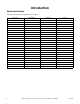
Introduction Model Identification Information in this manual is applicable to these models: 2 HC18NC2 HC80NRV NC60NC2 SC35NC2 HC18NR2 HC80NXV NC60NCF SC35NR2 HC18NX2 NC18NC2 NC60NR2 SC35NX2 HC25NC2 NC18NP2 NC60NRF SC40NC2 HC25NR2 NC18NR2 NC60NX2 SC40NR2 HC25NX2 NC18NX2 NC60NXF SC40NX2 HC27NC2 NC25NC2 NC80NCV SC50NC2 HC27NR2 NC25NP2 NC80NPV SC50NR2 HC27NX2 NC25NR2 NC80NRV SC50NX2 HC35NC2 NC25NX2 NC80NXV SC60NC2 HC35NR2 NC27NC2 SC18NC2 SC60NCF HC35NX2 NC27NP2 SC
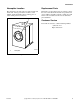
Introduction Nameplate Location Replacement Parts The nameplate is located at the rear of the machine and inside door. Always provide the machine’s serial number and model number when ordering parts or when seeking technical assistance. If literature or replacement parts are required, contact the source from whom the machine was purchased or contact Alliance Laundry Systems at (920) 748-3950 for the name and address of the nearest authorized parts distributor.
Safety Information Explanation of Safety Messages Precautionary statements (“DANGER,” “WARNING” and “CAUTION”), followed by specific instructions, are found in this manual and on machine decals. These precautions are intended for the personal safety of the operator, user, servicer and those maintaining the machine.
Safety Information 7. Before the washer is removed from service or discarded, remove the door to the washing compartment. 20. If the supply cord is damaged, it must be replaced by a special cord or assembly available from the manufacturer or its service agent. 8. Do not reach into the washer if the wash drum is moving. 21. Be sure water connections have a shut-off valve and that fill hose connections are tight. CLOSE the shut-off valves at the end of each wash day. 9.
Safety Information WARNING CAUTION This machine must be installed, adjusted, and serviced by qualified electrical maintenance personnel familiar with the construction and operation of this type of machinery. They must also be familiar with the potential hazards involved. Failure to observe this warning may result in personal injury and/or equipment damage, and may void the warranty. SW004 IMPORTANT: Ensure that the recommended clearances for inspection and maintenance are provided.
Safety Information Operator Safety Do not bypass any safety devices in the machine. WARNING WARNING NEVER insert hands or objects into basket until it has completely stopped. Doing so could result in serious injury. SW012 To ensure the safety of machine operators, the following maintenance checks must be performed daily: Never operate the machine with a bypassed or disconnected balance system.
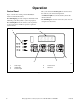
Operation Control Panel The cycle and wash selection pads are used to select the desired cycle and wash temperature. Figure 2 shows the control panel for NetMaster Control cardreader machines. An indicator light in each selection key shows the current selection. The VFD display provides vend price information and remaining cycle time (when a cycle is in progress). The START pad is used to start wash cycles once the vend price has been met.
Operation Operating Instructions 4. Close door and turn handle counterclockwise until button pops out. Refer to Figure 5. 1. Turn on the main power at its source (circuit breaker). 2. Push button and turn handle clockwise to open. Refer to Figure 3. U005I Figure 5 5. Select cycle and temperature. Refer to Figure 6. U001I U001I Figure 3 6. Insert coin(s) or card. To Insert Money 3. Load to capacity whenever possible. DO NOT OVERLOAD. Refer to Figure 4. 7. Check pricing as seen on digital display.
Operation To Insert Card 8. Insert card into opening. DO NOT REMOVE THE CARD UNTIL “REMOVE CARD” LED IS LIT. Refer to Figure 7 and Figure 8. NOTE: If a higher-priced cycle is selected after the full price has been satisfied for current cycle, display will show additional price required and the INSERT CARD light will flash. Insert card to satisfy price for special cycle. If price is not satisfied, the previous cycle selected will begin after one minute. 10.
Operation Power Failure Recovery Error Display Indications If a cycle is in progress and the power fails, cycle status is saved in memory (for a minimum of six years) without power being applied. An error is recoverable if normal machine function can resume without having to shut off power to the machine. See below for recoverable errors. If power resumes within 1 minute and 30 seconds, the previously active cycle will continue without having to press START.
Operation ● E:Ub – When computer is unable to balance a load during the drain step before the last extract step, computer will run the last extract step at lowest spin speed and display “E:Ub” for one minute after the door is opened. ● Alrm – When the computer senses a Break-In Alarm error caused by the service door and Coin Vault switches. ● Off – When the computer senses a Break-In Alarm error caused by the service door and Coin Vault switches and the “shut down” option is turned on.
Operation ● EC:xx – When the computer senses a Card Reader Communication error, the display will read “EC:xx” where “xx” indicates the error description as shown in Table 2. Error Display ● Right-most decimal point lit – When the computer senses a network communication error, the right-most decimal point will be lit.
Maintenance 3. Check door interlock before starting operation: WARNING Sharp edges can cause personal injury. Wear safety glasses and gloves, use proper tools and provide lighting when handling sheet metal parts. W366R1 IMPORTANT: Replace all panels that are removed to perform service and maintenance procedures. Do not operate the machine with missing guards or with broken or missing parts. Do not bypass any safety devices. Daily a. Attempt to start the machine with the door open.
Maintenance Weekly Monthly 1. For variable-speed models only, clean the AC drive box filter(s) weekly or more frequently as needed. NOTE: Disconnect power to the machine at its source before performing the monthly maintenance procedures. NOTE: If fan filter service indicator light is on, fan filter must be cleaned immediately to prevent possible damage. Thermostat automatically resets after drive compartment cools down. LED will then extinguish after cycle run. 1.
Maintenance c. For flat-pulley drive systems, verify allowable distance of belt from edge of pulley as shown in Table 3. Flat Pulley Alignment Model Allowable Distance from Edge 18 – 40 3/32 in. (2.4 mm) 50 – 60 3/8 in. (9.5 mm) 1 Table 3 2 d. For variable-speed models only, verify that V-belts are properly tensioned by applying a set force to the belt and measuring the deflection to determine the belt tension. Refer to Table 4 for the acceptable belt tension ranges.
Maintenance 1 2 H047I 1 2 Bearing Grease Fitting Seal Grease Fitting Figure 14 3. For 80 Pound capacity models only, lubricate bearings and seals each month OR after every 200 hours of operation. Refer to Figure 14. a. Use a premium-grade lithium-based #2 grease. Never mix two types of grease, such as petroleum and silicone. b.
Maintenance 9. Clean interior of machine, both basket and shell, by wiping with a water-soaked sponge or cloth. 6. Clean steam filter, where applicable. Refer to Figure 15. 10. Use compressed air to ensure that all electrical components are free of moisture and dust. a. Turn off steam supply and allow time for the valve to cool. 11. Verify the insulation is intact on all external wires and that all connections are secure. If bare wire is evident, call a service technician. b. Unscrew Cap. 12.
Maintenance Care of Stainless Steel ● Remove dirt and grease with detergent and water. Thoroughly rinse and dry after washing. ● Avoid contact with dissimilar metals to prevent galvanic corrosion when salty or acidic solutions are present. ● Do not allow salty or acidic solutions to evaporate and dry on stainless steel. Wipe clean of any residues. ● Rub in the direction of the polish lines or “grain” of the stainless steel to avoid scratch marks when using abrasive cleaners.