Operation/Maintenance Washer-Extractors Cabinet Hardmount B-Series Microcomputer for Coin Models 2 Speed and Variable-Speed Refer to Page 5 for Model Identification NOTA: El manual en español aparece después del manual en inglés. CHM166C Keep These Instructions for Future Reference. (If this machine changes ownership, this manual must accompany machine.) www.comlaundry.com Part No.
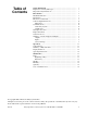
Table of Contents Safety Information.............................................................................. Explanation of Safety Messages........................................................... Important Safety Instructions ............................................................... 3 3 3 Introduction......................................................................................... Model Identification .............................................................................
Notes 2 © Copyright, Alliance Laundry Systems LLC – DO NOT COPY or TRANSMIT F232172
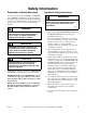
Safety Information Explanation of Safety Messages Precautionary statements (“DANGER,” “WARNING” and “CAUTION”), followed by specific instructions, are found in this manual and on machine decals. These precautions are intended for the personal safety of the operator, user, servicer and those maintaining the machine.
Safety Information 9. Do not install or store the washer where it will be exposed to water and/or weather. 10. Do not tamper with the controls. 11. Do not repair or replace any part of the washer, or attempt any servicing unless specifically recommended in the user-maintenance instructions or in published user-repair instructions that the user understands and has the skills to carry out. 12.
Introduction Model Identification Information in this manual is applicable to these models: HC20BC2 HC30BY2 HC60BX2 SC20BX2 SC40BL2 SC60BX2 HC20BL2 HC40BC2 HC60BXF SC20BY2 SC40BX2 SC60BXF HC20BX2 HC40BL2 HC60BYF SC25BC2 SC40BY2 SC60BYF HC20BY2 HC40BX2 HC60BY2 SC25BL2 SC50BC2 SC60BY2 HC25BC2 HC40BY2 HC80BCV SC25BX2 SC50BL2 SC80BCV HC25BL2 HC50BC2 HC80BLV SC25BY2 SC50BX2 SC80BLV HC25BX2 HC50BX2 HC80BXV SC30BC2 SC50BY2 SC80BNV HC25BY2 HC50BY2 HC80BYV SC30BL2 SC60BC
Introduction Control Output Fuse Board Communications This portion of the control contains the power supply for the control unit, and also the switching devices which power the components in the machine, all of which are on the output PC board. The switching devices are controlled by the control unit, and are solid state. Central Pay System Harnessing Wiring harnesses are modular – harnesses common to various configurations are similar, while those specific to a certain configuration can be added.
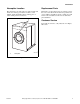
Introduction Nameplate Location Replacement Parts The nameplate is located at the rear of the machine and inside door. Always provide the machine’s serial number and model number when ordering parts or when seeking technical assistance. If literature or replacement parts are required, contact the source from whom the machine was purchased or contact Alliance Laundry Systems at (920) 748-3950 for the name and address of the nearest authorized parts distributor.
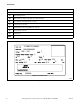
Introduction Model Number Familiarization Guide Sample Model Number: *C40BC2OU60001 *C Model Number Prefix 40 Washer-Extractor Capacity (pounds dry weight of laundry) B Type of Electrical Control (B = B – control) C Actuation (C = Coin drop) 2 Washer-Extractor Speed Capability (2 = 2 speed) O Electrical Characteristics U6 Design Series 0001 Option Identification (varies from machine to machine) * Denotes Brand *C40BC2OU60001 00000000000 208 – 240 7 3 60 3 60 N/A 3 18 470 N/A 0 50000
Introduction Summary of Control Outputs and Inputs Outputs General outputs provide signals to operate the following components. Control Voltage The control power supply can be configured to operate on 110 Volt AC nominal RMS input voltage 50/60 Hertz, OR 220 Volt AC nominal RMS input voltage 50/60 Hertz. 1. Hot Fill Valve 2. Cold Fill Valve 3. Drain Valve (normally open) 4. Door Lock Solenoid Coil 5. Door Unlock Solenoid Coil 6. Supply 1 (detergent) 7. Supply 2 (bleach) 8. Supply 3 (sour/softener) 9.
Notes 10 © Copyright, Alliance Laundry Systems LLC – DO NOT COPY or TRANSMIT F232172
Operation Control Panel 2 1 15 NORMAL 14 WASH ADD BLEACH 13 RINSE SPIN 12 HOT WARM NORMAL PERM PRESS WARM COLD QUICK WASH QUICK WASH HOT HEAVY SOIL 5 15 PERM PRESS 6 7 8 WARM DELICATE 95C 95C 60C 60C 6 14 13 7 12 START DOOR 11 2 1 5 40C 40C 8 11 30C 4 9 3 DOMESTIC MODELS 10 COLD CHM482R 9 3 4 INTERNATIONAL MODELS CHM482R 1 2 3 4 5 6 7 8 Cycle 1 Cycle 2 Cycle 3 Cycle 4/Up Edit Cycle 5 Cycle 6 Cycle 7/Set Up (*) Keypad † Cycle 8/Down Edit < HOT < 10 CHM488R CHM
Operation Display Indicators Table 2 lists the various displays and what they mean. The operator should become familiar with these machine displays.
Operation Table 2 (Continued) Display CAnt /OPEn COIn Control cannot unlock the door Control will interpret both coin inputs as signals from a drop coin meter meaning coins must fall through slot at a certain rate to be counted as valid coins. Con1/dEnO Denomination assigned for coin 1 input (example: .
Operation Operating Instructions 1. Turn on main power source (circuit breaker). 4. Close door and turn handle counterclockwise until button pops out. Refer to Figure 6. 2. Push button and turn handle clockwise to open. Refer to Figure 4. U005I U005I Figure 6 U001I U001I Figure 4 3. Load to capacity whenever possible. DO NOT OVERLOAD. Refer to Figure 5. 5. The default wash cycle will display. NOTE: Perm Press Cold is the default cycle if none is selected.
Operation 6. If desired, select a different cycle at this point or after satisfying vend. The LED indicator for that cycle will light. 7. Add liquid and/or powder supplies to supply dispenser. Refer to Figure 8. a. Add detergent to compartment 1. 10. If the unit is interfaced to a central/remote pay system, go to the central/remote pay console, make payment and select the machine. Contact the pay system manufacturer for more details. 11.
Notes 16 © Copyright, Alliance Laundry Systems LLC – DO NOT COPY or TRANSMIT F232172
Maintenance 4. Check door interlock before starting operation: WARNING Sharp edges can cause personal injury. Wear safety glasses and gloves, use proper tools and provide lighting when handling sheet metal parts. W366R1 IMPORTANT: Replace all panels that are removed to perform service and maintenance procedures. Do not operate the machine with missing guards or with broken or missing parts. Do not bypass any safety devices. Daily a. Attempt to start the machine with the door open.
Maintenance Weekly Monthly 1. For variable-speed models only, clean the AC drive box filter(s) weekly or more frequently as needed: NOTE: If fan filter service indicator light is on, fan filter must be cleaned immediately to prevent possible damage. Thermostat automatically resets after drive compartment cools down. LED will then extinguish after cycle run. IMPORTANT: If filter indicator is ignored, repeated resets might shorten life of drive. Clean filter regularly to avoid indicator prompt. a.
Maintenance c. For flat-pulley drive systems, verify allowable distance of belt from edge of pulley. Refer to Table 3 below. Flat-Pulley Alignment Model Allowable Distance from Edge 20 3/32 in. (2 mm) 25 3/32 in. (2 mm) 30 3/32 in. (2 mm) 40 3/32 in. (2 mm) 50 – 60 3/8 in. (10 mm) 1 2 H039I 1 2 Table 3 Deflection Span Length d.
Maintenance 1 2 H047I H047I 1 2 Bearing Grease Fitting Seal Grease Fitting Figure 11 2. For 80 pound capacity models only, lubricate bearings and seals each month OR after every 200 hours of operation. Refer to Figure 11. a. Use a premium-grade lithium-based #2 grease. Never mix two types of grease, such as petroleum and silicone. 20 b.
Maintenance 3. Remove back panel and check overflow hose and drain hose for leaks. 4. Unlock the hinged lid and check the supply dispenser hoses and hose connections. 4. Check all painted surfaces for exposed metal. (Matching paint is available from the manufacturer.) ● If bare metal is showing, paint with primer or solvent-based paint. ● If rust appears, remove it with sandpaper or by chemical means. 5. Clean inlet hose filter screens: a. Turn water off and allow valve to cool, if necessary.
Maintenance Care of Stainless Steel ● Remove dirt and grease with detergent and water. Thoroughly rinse and dry after washing. ● Avoid contact with dissimilar metals to prevent galvanic corrosion when salty or acidic solutions are present. ● Do not allow salty or acidic solutions to evaporate and dry on stainless steel. Wipe clean of any residues. ● Do not leave sanitizers or sterilizing solutions on stainless steel equipment for prolonged periods of time.