Installation/Operation Clothes Dryer Nonmetered and Metered Electric and Gas Models D677I Keep These Instructions for Future Reference. (If this machine changes ownership, this manual must accompany machine.) www.comlaundry.com Part No.
WARNING FOR YOUR SAFETY, the information in this manual must be followed to minimize the risk of fire or explosion or to prevent property damage, personal injury or death. W033 • Do not store or use gasoline or other flammable vapors and liquids in the vicinity of this or any other appliance. • WHAT TO DO IF YOU SMELL GAS: – Do not try to light any appliance. – Do not touch any electrical switch; do not use any phone in your building. – Clear the room, building or area of all occupants.
Table of Contents Safety Information.............................................................................. Explanation of Safety Messages........................................................... Important Safety Instructions ............................................................... 4 4 4 Installation........................................................................................... Dimensions .........................................................................................
Operation............................................................................................. Operation Instructions for Nonmetered and Coin Slide Dryers ........... Step 1: Clean Lint Filter................................................................... Step 2: Load Laundry....................................................................... Step 3: Close Loading Door............................................................. Step 4: Set Fabric Selector ....................................
Safety Information Explanation of Safety Messages Important Safety Instructions Throughout this manual and on machine decals, you will find precautionary statements (“DANGER,” “WARNING,” and “CAUTION”) followed by specific instructions. These precautions are intended for the personal safety of the operator, user, servicer, and those maintaining the machine. Save These Instructions DANGER Indicates an imminently hazardous situation that, if not avoided, will cause severe personal injury or death.
Safety Information 13. Keep area around the exhaust opening and adjacent surrounding area free from the accumulation of lint, dust and dirt. 14. The interior of the dryer and the exhaust duct should be cleaned periodically by qualified service personnel. 15.
Installation Dimensions Nonmetered Models 59.7 cm (23.5 in.) 71.1 cm (28 in.) *39.2 cm (15.44 in.) *109.22 cm (43 in.) *102 cm (40.19 in.) *11.4 cm (4.5 in.) 20.3 cm (8.0 in.) *91.4 cm (36 in.) 54.8 cm (21.56 in.) 39.1 cm (15.4 in.) 68.3 cm (26.875 in.) 1.02 cm (0.4 in.) *10.2 cm (4.0 in.) DRY2098N ELECTRIC MODELS DRY2098N *With leveling legs turned into base. NOTE: Exhaust openings are 10.2 cm (4 in.) metal ducting. 71.1 cm (28 in.) 1.02 cm (0.4 in.) *109.22 cm (43 in.) *39.2 cm (15.44 in.
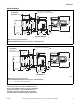
Installation Metered Models *102 cm (40.19 in.) Coin Slide Models 54.8 cm (21.56 in.) Coin Slide Models 56 cm (22.06 in.) Electronic Control Models 20.3 cm (8.0 in.) 59.7 cm (23.5 in.) *109.22 cm (43 in.) *39.2 cm (15.44 in.) *91.4 cm (36 in.) *11.4 cm (4.5 in.) *97 cm (38.19 in.) Electronic Control Models 39.1 cm (15.4 in.) 68.3 cm (26.875 in.) 1.02 cm (0.4 in.) 71.1 cm (28 in.) *10.2 cm (4.0 in.) ELECTRIC MODELS DRY2096N *With leveling legs turned into base. NOTE: Exhaust openings are 10.
Installation Before You Start Card Reader Models Tools For most installations, the basic tools you will need are: 1 2 3 The machine is shipped from the factory with the Electronic Control Diagnostic Harness Assembly unplugged. To avoid unauthorized manual programming or vending perform the following steps. 1. Open service door. Refer to Figure 2. 1. Locate diagnostic harness on electronic control. 2. Plug connectors for “white/black” wire and “red/ blue” wire together. .
Installation Installing the Dryer No other fuel burning appliance should be installed in the same closet with the dryer. Step 1: Position and Level the Dryer The dryer must not be installed or stored in an area where it will be exposed to water and/or weather. Install dryer before washer. This allows room for attaching exhaust duct. Install the four rubber feet (in accessories bag). Select a location with a solid floor.
Installation Place the dryer in position, and adjust the legs until the dryer is level from side to side and front to back. Leveling legs can be adjusted from inside the dryer with a 1/4 in. driver. All four legs must rest firmly on the floor so the weight of the dryer is evenly distributed. The dryer must not rock. Step 2: Connect Dryer Exhaust System WARNING To reduce the risk of fire and combustion gas accumulation the dryer MUST be exhausted to the outdoors.
Installation DO NOT use plastic or thin foil ducting. Rigid metal duct is recommended. Static pressure in exhaust duct should not be greater than 1.0 cm water column (.4 in.), measured with manometer placed on exhaust duct 61 cm (two feet) from dryer (check with dryer running and no load). In multi-dryer installations, all dryers connected to the main collector duct should be operating when pressure is checked.
Installation Exhaust Direction Exhaust System The dryer can be exhausted to the outdoors through the back, left, right or bottom of the dryer. EXCEPTION: Gas dryers cannot be vented out the left side because of the burner housing. For best drying results, recommended maximum length of exhaust system is shown in Table 1. To prevent backdraft when dryer is not in operation, outer end of exhaust pipe must have a weather hood with hinged dampers (obtain locally).
Installation Multi-Dryer Installation Exhaust Requirements Figure 6 shows a typical example of a multiple dryer installation. Note how each dryer has its own exhaust system vented to the central exhaust duct. 1 2 61 cm (24 in.) MINIMUM CLEARANCE TO ROOF/GROUND 3 METERED MODELS ILLUSTRATED D797I 1 2 58786 Backdraft Damper (Available through your local authorized parts source) Clean Out Cover (Must be provided). Inspect monthly.
Installation 1 A B C D E F G H I J 2 K 5 3 AIR FLOW 30° EXHAUST AIR FLOW MAXIMUM LENGTH OF DUCT 9.1 m (30 feet) 4 EXHAUST OUTLET 61 cm (24 in.) MINIMUM CLEARANCE TO ROOF/GROUND D686I HORIZONTAL EXHAUST INSTALLATION D686I 1 2 NOTE: Where the exhaust duct pierces a combustible wall or ceiling, the opening must be sized per local codes. Wall 3 4 5 5 cm (2 in.) Minimum or Clearance per Local Codes No Screen or Cap Clean Out Cover – Inspect Monthly Figure 7 WARNING 2 61 cm (24 in.
Installation Duct Station Minimum Diameter of Collector Duct A 10.2 cm (4 inches) B 20.3 cm (8 inches) C 22.9 cm (9 inches) D 25.4 cm (10 inches) E 27.9 cm (11 inches) F 30.5 cm (12 inches) G 32.6 cm (13 inches) H 35.6 cm (14 inches) I 38.1 cm (15 inches) J 38.1 cm (15 inches) K 40.6 cm (16 inches) 1. Make certain your dryer is equipped for use with the type of gas in your laundry room. Dryers with “23” in last two characters of model number: Dryer is equipped at the factory for L.
Installation L.P. (Liquefied Petroleum) Gas, 93.1 MJ/m3 (2500 Btu/ft3) service must be supplied at 10 ± 1.5 inch water column pressure. For proper operation at altitudes above 1070 m (3500 feet) the L.P. gas valve spud orifice size must be reduced to ensure complete combustion. Refer to Table 3. NOTE: When connecting to a gas line, an equipment shut-off valve must be installed within 1.8 m (6 feet) of the dryer. An 1/8 in. NPT pipe plug must be installed as shown for checking inlet pressure.
Installation Step 4: Reverse Door, if Desired 4. Rotate door panel 180 degrees as shown. The door on this dryer is completely reversible. To reverse door proceed as follows: 1. Remove four hinge attaching screws. D273P Figure 13 D675I D675I 5. Remove door strike from door liner and reinstall on opposite side. Figure 10 2. Remove all nine screws. DRY1917N DRY1917N Figure 14 6. Insert liner under flange on bottom of door, then push top of door liner into place. D272P Figure 11 3.
Installation 8. Using screwdriver, remove two door plugs, and reinstall on opposite side of door opening. Step 6: Connect the Dryer to Electrical Power 220 or 230 Volt, 50 or 60 Hertz, 2-Wire Plus Grounded (Earth) Wire Installation NOTE: Refer to dryer nameplate for proper voltage and Hertz dryer is designed to operate on. Refer to Figure 51 for nameplate location. NOTE: The wiring diagram is located inside the control hood. WARNING D317S D317S Figure 17 9.
Installation Models without Factory-Equipped Power Cord Use U.L. (Underwriters Laboratories) listed wire. Allow sufficient slack in wiring so dryer can be moved from its normal location when necessary. 1. Remove the screw and terminal block access cover from the rear of dryer cabinet. 2. Insert ends of direct wire through power supply hole (containing proper strain relief) in rear of dryer cabinet.
Installation WARNING Dryer is shown with the access cover removed for illustration purposes only. To reduce the risk of an electric shock, serious injury or death, NEVER operate the dryer with the access cover removed.
Installation Models without Factory-Equipped Plug Some models come without an electrical plug installed. If dryer is not hard wired (refer to Figure 21), a suitable plug that meets local electrical standards, including earthing requirements, must be installed. Refer to dryer nameplate for proper voltage and Hertz dryer is designed to operate on. Refer to Figure 51 for nameplate location.
Installation Models Factory-Equipped with Power Cord and Plug If the supply cord is damaged it must be replaced by a special cord or assembly available from the manufacturer or service agent. WARNING Improper connection of the equipmentearthing conductor can result in a risk of electric shock. Check with a qualified electrician or serviceman if you are in doubt as to whether the dryer is properly earthed. Earthing Instructions The dryer must be earthed.
Installation Step 7: Recheck Steps 1-6 Refer to Installer Checklist on the back cover of this manual and make sure that dryer is installed correctly. Step 8: Check Heat Source Electric Dryers Close the loading door and start the dryer in a heat setting (refer to the Operation section). After the dryer has operated for three minutes, the exhaust air or exhaust pipe should be warm. IMPORTANT: If igniter does not light, make sure gas is turned on.
Vending Meter Case End of Cycle Mode (Metered Models) In End of Cycle Mode, a cycle is complete and the IN USE LED is off. The control remains in this mode until the door is opened or additional vend has been satisfied. The factory mounted coin meter case does not include the service door lock, coin drawer, coin drawer lock and keys. These parts must be ordered (at extra cost) according to the purchaser’s requirements direct from the manufacturer of your choice.
Vending Error Display Mode Models Through Serial No. 0908 The control enters Error Display Mode to display thermistor errors. The heater is turned off, the IN USE LED flashes to indicate the error (refer to paragraphs below), and the timer will continue to count down time. The control remains in Error Display Mode until the control senses the thermistor has returned to an acceptable heating range, the cycle ends or machine is powered down.
Vending Dipswitch Settings Heat Switch Number Heat Time Per Coin Pulse (in minutes) 1 2 3 4 5 6 1 OFF OFF OFF OFF OFF OFF 2 ON OFF OFF OFF OFF OFF 3 OFF ON OFF OFF OFF OFF 4 ON ON OFF OFF OFF OFF 5 OFF OFF ON OFF OFF OFF 6 ON OFF ON OFF OFF OFF 7 OFF ON ON OFF OFF OFF 8 ON ON ON OFF OFF OFF 9 OFF OFF OFF ON OFF OFF 10 ON OFF OFF ON OFF OFF 11 OFF ON OFF ON OFF OFF 12 ON ON OFF ON OFF OFF 13 OFF OFF ON ON OFF OF
Vending Table 5 (continued) Heat Switch Number Heat Time Per Coin Pulse (in minutes) 1 2 3 4 5 6 39 OFF ON ON OFF OFF ON 40 ON ON ON OFF OFF ON 41 OFF OFF OFF ON OFF ON 42 (preset at factory) ON OFF OFF ON OFF ON 43 OFF ON OFF ON OFF ON 44 ON ON OFF ON OFF ON 45 OFF OFF ON ON OFF ON 46 ON OFF ON ON OFF ON 47 OFF ON ON ON OFF ON 48 ON ON ON ON OFF ON 49 OFF OFF OFF OFF ON ON 50 ON OFF OFF OFF ON ON 51 OFF ON OFF OF
Vending Table 5 (continued) Models Starting Serial No 0909 Cool Down Per Cycle Cool Down Switch Number Cycle Reset Switch Number (in minutes) 7 8 3 (preset at factory) OFF OFF 6 ON ON Total Cycle Time = Heat Time + Cool Down Time Table 5 Test Setting 3. Plug in the machine and initiate a cycle. When testing coin slide operation or other troubleshooting, set dipswitch with this shorter cycle: 1. Unplug the machine power cord. 2. Record the machine control dipswitch settings.
Vending Slide Extension 5. Torque nut between 2 and 2.26 Nm (18 and 20 inch-pounds), or tighten nut firmly. (Coin Slide Models Only) 6. Install extension spring in bracket hole and hole in upper arm of lever. Refer to Figure 26. 1. Remove slide extension parts from parts accessories bag included in unit. 2. If installing a Greenwald coin slide, position extension lever (to be installed on extension bracket) with arm that has one star facing down. Refer to Figure 25. Greenwald Coin Slide 7.
Vending NOTE: During coin slide installation, make sure activation lever is up and off the switch. Refer to Figure 28. 1 Additional Dryer Security Located on the service door of the dryer is a flat Phillips head screw. During shipment, this screw is used to attach the service door to the meter case. For additional security, this screw can be reinstalled inside the control hood of your dryer. Following is the procedure for installing this screw: 1. Remove the Phillips head screw from service door.
Operation Operation Instructions for Nonmetered and Coin Slide Dryers WARNING To reduce the risk of fire, electric shock, or injury to persons, read the IMPORTANT SAFETY INSTRUCTIONS before operating this appliance. Step 2: Load Laundry Load clothes loosely into dryer drum. Add fabric softener sheet if desired. IMPORTANT: To avoid damage to dryer, do not use more than one fabric softener sheet per load.
Operation Step 4: Set Fabric Selector Coin Slide Models Select NORMAL for cottons, PERM PRESS for permanent press, DELICATE for sensitive items or FLUFF (NO HEAT) for items that require no heat. Place coin(s) in slide and carefully push in as far as possible and then pull slide out as far as possible. After IN USE light comes on (indicating start of cycle), press the PUSH-TO-START button. NOTE: Always follow manufacturer’s care label instructions.
Operation Operation Instructions for MDC Dryers Step 2: Load Laundry Load clothes loosely into dryer drum. Add fabric softener sheet if desired. WARNING To reduce the risk of fire, electric shock, or injury to persons, read the IMPORTANT SAFETY INSTRUCTIONS before operating this appliance. IMPORTANT: To avoid damage to dryer, do not use more than one fabric softener sheet per load.
Operation Step 4: Set Fabric Selector Select HIGH TEMP, MED TEMP, LOW TEMP or DELICATES by pushing touchpad. NOTE: Always follow manufacturer’s care label instructions. If Additional Time Feature is turned on, additional dryer time may be purchased at cycle start or while dryer is running. Remove knits when slightly damp because overdrying may cause shrinkage. Do not tumble dry knit woolens. Step 6: Start Dryer To start dryer, push START pad. To stop dryer at any time, open the door.
Operation Operation Instructions for NetMaster Dryers Step 2: Load Laundry Load clothes loosely into dryer drum. Add fabric softener sheet if desired. WARNING To reduce the risk of fire, electric shock, or injury to persons, read the IMPORTANT SAFETY INSTRUCTIONS before operating this appliance. IMPORTANT: To avoid damage to dryer, do not use more than one fabric softener sheet per load.
Operation Step 4: Set Fabric Selector To Insert Card Select HIGH TEMP, MED TEMP, LOW TEMP or NO HEAT by pushing touchpad. Insert card into opening. DO NOT remove the card until the REMOVE CARD LED is lit. NOTE: Always follow manufacturer’s care label instructions. D777I D777I Figure 46 M343I Figure 48 To Insert Money If Additional Time Feature is turned on, additional dryer time may be purchased at cycle start or while dryer is running. Insert coin(s) in coin slot.
Operation Indicator Lights COOL DOWN INSERT COINS/CARD COOL DOWN is lit whenever the COOL DOWN portion of a heated cycle is active. It is also lit when the NO HEAT cycle is in operation. INSERT COINS/CARD is lit to prompt the user to insert coins or a card to satisfy the vend price. When INSERT COINS/CARD is lit, the three digits and decimal point will display the vend price remaining to be satisfied.
Maintenance Lubrication Exhaust System All moving parts are sealed in a permanent supply of lubricant or are equipped with oilless bearings. Additional lubrication will not be necessary. WARNING To reduce the risk of electric shock, disconnect the electrical service to the dryer before cleaning. Care of Your Dryer WARNING W043 To reduce the risk of an electric shock, serious injury or death, disconnect the electrical service to the dryer before cleaning the interior.
Maintenance Lint Filter For Energy Conservation CLEAN THE LINT FILTER BEFORE DRYING EACH LOAD. (Refer to Figure 50 for lint filter location.) Cleaning the lint filter is important because a layer or pad of lint on the filter will block the flow of air through the dryer, thus reducing the efficiency of the dryer. The clothes will take longer to dry and energy will be wasted. The lint filter may be washed if needed. Annually remove lint filter and screw to vacuum the duct under it.
Troubleshooting Try these troubleshooting tips before making a service call – You may save time and money! Dryer Symptom Possible Cause/Solution Dryer won’t start Dryer won’t heat Dryer doesn’t dry clothes satisfactorily Dryer is noisy Nonmetered models - Turn timer knob further into cycle. Metered models - Insert coin(s) or card. Metered models - Activate timer. Push coin slide all the way in.
Contact Information If service is required, contact the nearest Factory Authorized Service Center. WARNING If you are unable to locate an authorized service center or are unsatisfied with the service performed on your dryer, contact: Alliance Laundry Systems Shepard Street P. O. Box 990 Ripon, WI 54971-0990 U.S.A. www. comlaundry.
Installer Checklist Fast Track for Installing the Dryer (Refer to the manual for more detailed information) 1 5 • Position and Level the Dryer. • Wipe Out Inside of Dryer. LEVEL D255I D255I D256I CHECK 2 D335I GAS ONLY • Connect Gas Supply Pipe Hoses. • Check for Gas Leaks. 7 D258I D703IE0A D703IE0A • Recheck Steps 1-6. CHECK 8 • Reverse Door, if Desired. D610I D610I • Connect the Dryer to Electrical Power. CHECK D335I D333I D333I CHECK 4 6 • Connect Dryer Exhaust System.