Pocket Hardmount Variable-Speed PS40 Control Refer to Page 4 for Model Identification Installation/Operation Supplement Washer-Extractors PHM1397C PHM1397C Keep These Instructions for Future Reference. (If this machine changes ownership, this manual must accompany machine.) www.comlaundry.com Part No.
Installation/Operation Supplement Table of Contents Safety Information.............................................................................. Explanation of Safety Messages........................................................... Important Safety Instructions ............................................................... Model Identification ............................................................................. 2 2 2 4 Specifications and Dimensions.......................................
Installation/Operation Supplement Safety Information Explanation of Safety Messages Precautionary statements (“DANGER,” “WARNING,” and “CAUTION”), followed by specific instructions, are found in this manual and on machine decals. These precautions are intended for the personal safety of the operator, user, servicer, and those maintaining the machine.
Installation/Operation Supplement 9. Do not install or store the washer where it will be exposed to water and/or weather. 10. Do not tamper with the controls. 11. Do not repair or replace any part of the washer, or attempt any servicing unless specifically recommended in the user-maintenance instructions or in published user-repair instructions that the user understands and has the skills to carry out. 12.
Installation/Operation Supplement Model Identification Information in this manual is applicable to these models: Medium Speed 40 Pound IP040PMQ1 IP040PMX1 IPH40M IPH180 CP040PHN1 CP040PHQ1 CP040PHX1 CPC40H IP040PHN1 IP040PHQ1 IP040PHX1 IPH40H JP040PHN1 JP040PHQ1 60 Pound CP060PMN1 CP060PMQ1 CP060PMX1 CPC60M IP060PMN1 IP060PMQ1 IP060PMX1 IPH60M IPH270 JP060PMQ1 CP060PHN1 CP060PHQ1 CP060PHX1 CPC60H IP060PHN1 IP060PHQ1 IP060PHX1 IPH60H JP060PHN1 JP060PHQ1 80 Pound CP080PMN1 CP080PMQ1 CPC80M IP080PM
Installation/Operation Supplement Specifications and Dimensions High Speed Models Models Specifications 40H 60H 80H 100H 125H 140H 175H Overall Width, mm (in.) 813 (32) 876 (34.5) 1080 (42.5) 1080 (42.5) 1430 (56.3) 1430 (56.3) 1430 (56.3) Overall Height, mm (in.) 1448 (57) 1590 (62.6) 1778 (70) 1778 (70) 1958 (77.1) 1958 (77.1) 1958 (77.1) Overall Depth, mm (in.) 1158 (45.6) 1213 (47.8) 1306 (51.4) 1433 (56.4) 1425 (56.1) 1502 (59.
Installation/Operation Supplement Table 1 (continued) Models Specifications 40H 60H 80H 100H 125H 140H 175H 3/4 NPT 3/4 NPT 3/4 NPT 3/4 NPT 3/4 NPT 1-1/4 NPT 1-1/4 NPT 2/3 2/3 2/3 2/3 2/3 2/3 2/3 Number of Dry Chemical Compartments, (std/opt) 1/5 1/5 1/5 1/5 1/5 1/5 1/5 Number of Liquid Supply Connections, (std/opt) 6/12 6/12 6/12 6/12 6/12 6/12 6/12 Water Inlet Connection Size Number of Inlets, (std/opt) Chemical Supply System Cylinder Speeds/Centrifugal Force Data 0
Installation/Operation Supplement Table 1 (continued) Specifications 40H 60H 80H 100H 125H 140H 175H Max. Circuit Breaker Size (200-240V, 3P) 15 15 20 20 30 30 Not Applicable Max. Circuit Breaker Size (380-480V, 3P) 15 15 15 15 15 15 20 All specifications are subject to change without notification.
Installation/Operation Supplement Medium Speed Models Models Specifications 40M 60M 80M 100M 140M Overall Width, mm (in.) 813 (32) 876 (34.5) 1080 (42.5) 1080 (42.5) 1276 (50.3) Overall Height, mm (in.) 1448 (57) 1590 (62.6) 1778 (70) 1778 (70) 1958 (77.1) Overall Depth, mm (in.) 1158 (45.6) 1213 (47.8) 1306 (51.4) 1433 (56.4) 1502 (59.1) Net Weight, kg (lbs.) 499 (110) 533 (1175) 740 (1630) 804 (1770) 1044 (2300) Domestic Shipping Weight, kg (lbs.
Installation/Operation Supplement Table 2 (continued) Models Specifications 40M 60M 80M 100M 140M Number of Dry Chemical compartments, (std/opt) 1/5 1/5 1/5 1/5 1/5 Number of Liquid Supply Connections, (std/opt) 6/12 6/12 6/12 6/12 6/12 1/2 NPT 1/2 NPT 1/2 NPT 1/2 NPT 1/2 NPT 1 1 1 1 1 2.3 (3) 2.3 (3) 3.7 (5) 3.7 (5) 5.6 (7.5) 0.014 (6) 0.016 (6) 0.019 (6) 0.019 (6) 0.022 (6) Wash Speed, G-Force (RPM) 0.8 (46) 0.8 (43) 0.8 (39) 0.8 (39) 0.
Installation/Operation Supplement Machine Dimensions Dimensional Clearances Allow a minimum of 600 mm (24 in.) at the rear and 450 mm (18 in.) at the sides for maintenance, inspection, and adjustment. Allow at least 450 mm (18 in.) between machines in multiple installations. Machine dimensions are indicated in Figure 1 through Figure 7. For minimum clearances, refer to Figure 9. 10 NOTE: The dimensions shown here are for planning purposes only.
Installation/Operation Supplement 40 Pound Models L 4 K 3 1 5 J 2 6 7 A E F C O G N H M D I B P 10 8 9 PHM727N REAR FRONT TOP PHM727N 1 2 3 4 5 External Supply Connection Auxiliary Hot Water Cold Water Greasing Points 6 7 8 9 10 External Supply Wiring Connection Power Inlet Steam Inlet Auxiliary Drain Drain Figure 1 A 1158 mm (45.6 in.) I 297 mm (11.7 in.) B 813 mm (32 in.) J 260 mm (10.25 in.) C 648 mm (25.5 in.) K 491 mm (19.35 in.) D 572 mm (22.5 in.
Installation/Operation Supplement 60 Pound Models M 4 L 3 1 5 K 2 6 7 10 A E C F G O H N I D J B P 9 8 TOP PHM728N REAR FRONT PHM728N 1 2 3 4 5 External Supply Connection Auxiliary Hot Water Cold Water Greasing Points 6 7 8 9 10 External Supply Wiring Connection Power Inlet Auxiliary Drain Drain Steam Inlet Figure 2 A 1213 mm (47.8 in.) I 978 mm (38.5 in.) B 876 mm (34.5 in.) J 297 mm (11.7 in.) C 732 mm (28.8 in.) K 292 mm (11.5 in.) D 656 mm (25.8 in.
Installation/Operation Supplement 80 Pound Models O 1 N 4 3 2 5 M 6 7 10 A G F E C H I P J Q K D L B R S 9 8 TOP PHM729N REAR FRONT PHM729N 1 2 3 4 5 External Supply Connection Auxiliary Hot Water Cold Water Greasing Points 6 7 8 9 10 External Supply Wiring Connection Power Inlet Auxiliary Drain 76.2 mm (3 in.) Drain Steam Inlet Figure 3 A 1306 mm (51.4 in.) K 975 mm (38.4 in.) B 1080 mm (42.5 in.) L 297 mm (11.7 in.) C 752 mm (29.6 in.) M 311 mm (12.25 in.
Installation/Operation Supplement 100 Pound Models O 1 N 4 3 2 5 M 6 7 10 A F G H E I Q P J I K C D L B S TOP 9 R 8 REAR FRONT PHM730N PHM730N 1 2 3 4 5 External Supply Connection Auxiliary Hot Water Cold Water Greasing Points 6 7 8 9 10 External Supply Wiring Connection Power Inlet Auxiliary Drain 76.2 mm (3 in.) Drain Steam Inlet Figure 4 A 1433 mm (56.4 in.) K 975 mm (38.4 in.) B 1080 mm (42.5 in.) L 297 mm (11.7 in.) C 765 mm (30.12 in.) M 311 mm (12.25 in.
Installation/Operation Supplement 125 Pound Models Q O 3 P N 4 5 2 6 1 9 G A H F E C I J R K L D M B T U TOP S REAR FRONT 8 7 PHM731N 1 2 3 4 5 External Supply Connection Hot Water Cold Water Auxiliary External Supply Wiring Connection 6 7 8 9 Power Inlet 76.2 mm (3 in.) Drain Auxiliary Drain Steam Inlet Figure 5 A 1425 mm (56.1 in.) L 1149 mm (45.3 in.) B 1278 mm (50.3 in.) M 294 mm (11.6 in.) C 871 mm (34.3 in.) N 171 mm (6.7 in.) D 795 mm (31.3 in.
Installation/Operation Supplement 140 Pound Models P O N 3 2 M L 4 5 1 G A F E 6 R H 10 Q I C D 7 J K B S T TOP 9 8 FRONT REAR PHM732N PHM732N 1 2 3 4 5 External Supply Connection Cold Water Hot Water Auxiliary External Supply Wiring Connection 6 7 8 9 10 Power Inlet Greasing Points Auxiliary Drain 76.2 mm (3 in.) Drain Steam Inlet Figure 6 A 1502 mm (59.1 in.) K 297 mm (11.7 in.) B 1275 mm (50.3 in.) L 305 mm (12 in.) C 871 mm (34.3 in.) M 386 mm (15.18 in.
Installation/Operation Supplement 175 Pound Models P O N 3 2 M L 4 5 1 G A F C R 10 H Q I E 6 7 J D K B S T TOP 9 8 FRONT REAR PHM733N 1 2 3 4 5 External Supply Connection Cold Water Hot Water Auxiliary External Supply Wiring Connection 6 7 8 9 10 Power Inlet Greasing Points Auxiliary Drain 76.2 mm (3 in.) Drain Steam Inlet Figure 7 A 1628 mm (64.1 in.) K 297 mm (11.7 in.) B 1276 mm (50.3 in.) L 305 mm (12 in.) C 871 mm (34.3 in.) M 386 mm (15.18 in.) D 795 mm (31.
Installation/Operation Supplement Front and Rear Features 5 11 6 12 10 13 14 4 3 2 9 15 8 7 1 16 FRONT PHM687N REAR PHM687N 1 2 3 4 5 6 7 8 Front Service Panel Door Release Panel Door Handle Loading Door Control Panel Supply Dispenser Rear Service Panel Steam Service Connection 9 10 11 12 13 14 15 16 Chemical Service Connection Water Service Connections Lubrication Points for Bearings Top Service Panel Chemical Signal Control Connection Power Service Connection Cooling Fan and Filter Drain Se
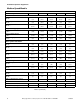
C002882 Floor Load Data Height of Basket Center (in.) Max RPM G Calculated Static Load (lbs.) Static Floor Pressure (lbs./ft.2) Dynamic Load (lbs.) Max Vertical Load (lbs.) Max Dynamic Floor Pressure (lbs./ft.2) Base Moment (lbs./ft.) Load Freq (Hz) Basket Diameter 40M 100G 27 1583 33.35 511 100 1701 179 786 2440 256.8 2185 8.52 40M 150G 27 1583 33.35 625 149.6 1701 179 706 2359 248.3 1961 10.42 40H 230G 27 1690 33.35 775 230 1808 190.3 1808 3569 375.
Height of Basket Center (in.) Max RPM G Calculated Static Load (lbs.) Static Floor Pressure (lbs./ft.2) Dynamic Load (lbs.) Max Vertical Load (lbs.) Max Dynamic Floor Pressure (lbs./ft.2) Base Moment (lbs./ft.) Load Freq (Hz) © Copyright, Alliance Laundry Systems LLC – DO NOT COPY or TRANSMIT Machine Size Basket Diameter Net Wt. of Machine (lbs.) 125H 200G 43 2749 46.5 573 200.3 3124 165.8 5006 7980 423.6 19400 9.55 125H 300G 43 2749 46.5 701 299.7 3124 165.
Installation/Operation Supplement Installation Instructions Mounting Surface These machines must be securely anchored on a solid, flat reinforced concrete surface capable of withstanding the weight of the machine and the considerable forces generated during the spin/extract cycle. Surface should be a high quality concrete (minimum 3500 psi test strength) and at least 305 mm (12 in.) thickness for all models. The surface shall be clean, flat and free of irregularities. The pad should be 305 mm (12 in.
Installation/Operation Supplement Mounting Bolt Installation Requirements All machine dimensions are subject to manufacturing tolerances and design revisions. All specifications are subject to change without notice. If precise machine dimensions are required for construction, consult the manufacturer for verification. Location Plan the location of the machines.
Installation/Operation Supplement 40 Pound Models WALL 610 MM (24 IN.) MIN.
Installation/Operation Supplement 40 Pound A 156 mm (6.125 in.) I 581 mm (22.88 in.) B 25 mm (1 in.) J 883 mm (34.75 in.) C 140 mm (5.5 in.) K 694 mm (27.31 in.) D 775 mm (30.5 in.) L 940 mm (37 in.) E 445 mm (17.5 in.) M 1087 mm (42.81 in.) F 229 mm (9 in.) N 533 mm (21 in.) G 156 mm (6.13 in.) O 762 mm (30 in.) H 795 mm (31.31 in.) P 813 mm (32 in.
Installation/Operation Supplement 60, 80 and 100 Pound Models WALL 610 MM (24 IN.) MIN.
Installation/Operation Supplement 60 Pound 80 Pound 100 Pound A 116 mm (4.56 in.) 67 mm (2.63 in.) 194 mm (7.63 in.) B 38 mm (1.5 in.) 38 mm (1.5 in.) 38 mm (1.5 in.) C 140 mm (5.5 in.) 178 mm (7 in.) 178 mm (7 in.) D 889 mm (35 in.) 1054 mm (41.5 in.) 1054 mm (41.5 in.) E 667 mm (26.25 in.) 838 mm (33 in.) 838 mm (33 in.) F 445 mm (17.5 in.) 559 mm (22 in.) 559 mm (22 in.) G 222 mm (8.75 in.) 279 mm (11 in.) 279 mm (11 in.) H 116 mm (4.56 in.) 122 mm (4.81 in.) 122 mm (4.
Installation/Operation Supplement 125, 140 and 175 Pound Models WALL 610 MM (24 IN.) MIN.
Installation/Operation Supplement 125 Pound 140 Pound 175 Pound A 102 mm (4 in.) 118 mm (4.63 in.) 118 mm (4.63 in.) B 38 mm (1.5 in.) 38 mm (1.5 in.) 38 mm (1.5 in.) C 178 mm (7 in.) 178 mm (7 in.) 178 mm (7 in.) D 1207 mm (47.5 in.) 1245 mm (49 in.) 1496 mm (58.88 in.) E 686 mm (27 in.) 686 mm (27 in.) 810 mm (31.88 in.) F 457 mm (18 in.) 457 mm (18 in.) 581 mm (22.88 in.) G 229 mm (9 in.) 229 mm (9 in.) 353 mm (13.88 in.) H 89 mm (3.5 in.) 124 mm (4.88 in.) 124 mm (4.
Installation/Operation Supplement Provisions for 50 Hz Installations If machine is to be installed on a 50 Hz power system, adjust control transformer taps as described in Installation manual. Then change drain valve wiring as follows: 1. Disconnect power from machine. Follow lockout/tag-out procedures. 1 2. Remove lower rear panel to acess drain valves. 50Hz 3. Snap black plastic cover off of each drain valve motor by locating and squeezing two tabs on each cover. 60Hz N PHM695N 4.
Installation/Operation Supplement Pocket Hardmount Electrical Specifications mm2 140M AWG 100M Breaker 80M Full Load Amps 60M mm2 40M AWG 175H Breaker 140H Full Load Amps 125H Wire 100H Phase 80H Cycle 60H Electric Heat Voltage 40H Standard Code Model Voltage Designation N 380 – 480 50/60 3 3 4 15 14 2.5 29 35 8 10 Q 200 – 240 50/60 3 3 8 15 14 2.5 56 60 6 16 N 380 – 480 50/60 3 3 6 15 14 2.
Installation/Operation Supplement Operation 2 1 4 3 5 6 RUN PROG 1 2 3 4 5 6 7 8 9 PS40 0 12 PHM1398C 11 10 9 8 7 PHM1398C 1 2 3 4 5 6 Stop Button Start Button Main Display Program Number/Alarm Display Emergency Stop Button Run/Program Mode Key Switch 7 8 9 10 11 12 Infra-Red Programming Port Enter Button Temperature/Toggle Button Up Button Down Button Number Buttons Figure 14 C002882 © Copyright, Alliance Laundry Systems LLC – DO NOT COPY or TRANSMIT 31
Installation/Operation Supplement General Operation Instructions 1. Make sure machine has been installed properly and that water and electrical services are on. 2. Sort laundry according to care labels, type, etc. WARNING Never use flammable materials of any kind in the machine! Never use any solvent other than water! 3. Open door and make sure that machine is empty. W686 4. Load goods to be processed into drum. Operating PS40 Control 5.
Installation/Operation Supplement Tips: Clearing an Alarm: 1. Note alarm code flashing on program display in order to look it up and correct problem. 2. Press ENTER button and display will be cleared. PS40 control will continue running normally. An alarm code indicates a potential machine problem or condition that should be examined. Clearing a Fault: 1. Note fault code flashing on program display in order to look it up and explain problem to a qualified technician. 2.
Installation/Operation Supplement Disposal of Unit This appliance is marked according to the European directive 2002/96/EC on Waste Electrical and Electronic Equipment (WEEE). This symbol on the product or on its packaging indicates that this product shall not be treated as household waste. Refer to Figure 15. Instead it shall be handed over to the applicable collection point for the recycling of electrical and electronic equipment.