Pocket Hardmount Variable-Speed PS40 Control Refer to Page 9 for Model Identification . Para bajar una copia de estas instrucciones en español, visite www.comlaundry.com PHM1397C PHM1397C Keep These Instructions for Future Reference. (If this machine changes ownership, this manual must accompany machine.) www.comlaundry.com Part No.
Table of Contents Safety Information.............................................................................. Explanation of Safety Messages........................................................... Important Safety Instructions ............................................................... Safety Decals ........................................................................................ Operator Safety.....................................................................................
Making Connections to Machine ..................................................... Adjusting Control Transformer Taps............................................... Provisions for 50 Hz Installations.................................................... Steam Requirements (Steam Heat Option Only).................................. Chemical Injection Supply System....................................................... Chemical Service Connections ........................................................
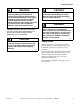
Safety Information Explanation of Safety Messages Precautionary statements (“DANGER,” “WARNING,” and “CAUTION”), followed by specific instructions, are found in this manual and on machine decals. These precautions are intended for the personal safety of the operator, user, servicer, and those maintaining the machine. Important Safety Instructions WARNING To reduce the risk of fire, electric shock, serious injury or death to persons when using your washer, follow these basic precautions: W023 DANGER 1.
Safety Information 9. Do not install or store the washer where it will be exposed to water and/or weather. 10. Do not tamper with the controls. 11. Do not repair or replace any part of the washer, or attempt any servicing unless specifically recommended in the user-maintenance instructions or in published user-repair instructions that the user understands and has the skills to carry out. 12.
Safety Information WARNING CAUTION This machine must be installed, adjusted, and serviced by qualified electrical maintenance personnel familiar with the construction and operation of this type of machinery. They must also be familiar with the potential hazards involved. Failure to observe this warning may result in personal injury and/or equipment damage, and may void the warranty. SW004 IMPORTANT: Ensure that the recommended clearances for inspection and maintenance are provided.
Safety Information Operator Safety Safe Operating Environment WARNING NEVER insert hands or objects into basket until it has completely stopped. Doing so could result in serious injury. SW012 To ensure the safety of machine operators, the following maintenance checks must be performed daily: Safe operation requires an appropriate operating environment for both the operator and the machine. If questions regarding safety arise, contact the manufacturer immediately.
Safety Information Input and Output Services DANGER Do not place volatile or flammable fluids in any machine. Do not clean the machine with volatile or flammable fluids such as acetone, lacquer thinners, enamel reducers, carbon tetrachloride, gasoline, benzene, naptha, etc. Doing so could result in serious personal injury and/or damage to the machine. SW002 ● ● Water Pressure. Best performance will be realized if water is provided at a pressure of 30 – 85 psi (2 – 5.7 bar).
Safety Information DirectDrive ● Machines equipped with DirectDrive require special attention with regard to operating environment. ● ● 8 An especially dusty or linty environment will require more frequent cleaning of AC inverter drive cooling fan filter and of AC inverter drive itself. Power line fluctuations from sources such as uninterruptible power supplies (UPS) can adversely affect machines equipped with AC inverter drive.
Safety Information Model Identification Information in this manual is applicable to these models: Medium Speed High Speed 40 Pound CP040PMN1 CP040PMQ1 CP040PMX1 CPC40M IP040PMN1 IP040PMQ1 IP040PMX1 IPH40M IPH180 CP040PHN1 CP040PHQ1 CP040PHX1 CPC40H IP040PHN1 IP040PHQ1 IP040PHX1 IPH40H JP040PHN1 JP040PHQ1 60 Pound CP060PMN1 CP060PMQ1 CP060PMX1 CPC60M IP060PMN1 IP060PMQ1 IP060PMX1 IPH60M IPH270 JP060PMQ1 CP060PHN1 CP060PHQ1 CP060PHX1 CPC60H IP060PHN1 IP060PHQ1 IP060PHX1 IPH60H JP060PHN1 JP060PHQ1
Introduction This manual is designed as a guide for the installation of a washer-extractor equipped with DirectDrive. NOTE: All information, illustrations and specifications contained in this manual are based on the latest product information available at the time of printing. We reserve the right to make changes at any time without notice. Delivery Inspection Upon delivery, visually inspect crate, protective cover and unit for any visible shipping damage.
Specifications and Dimensions High Speed Models . Models Specifications 40H 60H 80H 100H 125H 140H 175H Overall Width, in. (mm) 32 (813) 34.5 (876) 42.5 (1080) 42.5 (1080) 56.3 (1430) 56.3 (1276) 56.3 (1276) Overall Height, in. (mm) 57 (1448) 62.6 (1590) 70 (1778) 70 (1778) 77.1 (1958) 77.1 (1958) 77.1 (1958) Overall Depth, in. (mm) 45.6 (1158) 47.8 (1213) 51.4 (1306) 56.4 (1433) 56.1 (1425) 59.
Specifications and Dimensions Table 1 (continued) Models Specifications 40H 60H 80H 100H 125H 140H 175H 3/4 NPT 3/4 NPT 3/4 NPT 3/4 NPT 3/4 NPT 1-1/4 NPT 1-1/4 NPT 2/3 2/3 2/3 2/3 2/3 2/3 2/3 Number of Dry Chemical Compartments, (std/opt) 1/5 1/5 1/5 1/5 1/5 1/5 1/5 Number of Liquid Supply Connections, (std/opt) 6/12 6/12 6/12 6/12 6/12 6/12 6/12 Water Inlet Connection Size Number of Inlets, (std/opt) Chemical Supply System Cylinder Speeds/Centrifugal Force Data 6 (0.
Specifications and Dimensions Table 1 (continued) Models Specifications 40H 60H 80H 100H 125H 140H 175H Electrical Connections (Non-electric Heated Models) Max. Circuit Breaker Size (200-240V, 3P) 15 15 20 20 30 30 Not Applicable Max. Circuit Breaker Size (380-480V, 3P) 15 15 15 15 15 15 20 Table 1 All specifications are subject to change without notification.
Specifications and Dimensions Medium Speed Models . Models Specifications 40M 60M 80M 100M 140M Overall Width, in. (mm) 32 (813) 34.5 (876) 42 (1080) 42.5 (1080) 50.3 (1276) Overall Height, in. (mm) 57 (1448) 62.6 (1590) 70 (1778) 70 (1778) 77.1 (1958) Overall Depth, in. (mm) 45.6 (1158) 47.8 (1213) 51.4 (1306) 56.4 (1433) 59.1 (1502) Overall Dimensions Weight and Shipping Information Net Weight, lbs.
Specifications and Dimensions Table 2 (continued) Models Specifications 40M 60M 80M 100M 140M Number of Dry Chemical compartments, (std/opt) 1/5 1/5 1/5 1/5 1/5 Number of Liquid Supply Connections, (std/opt) 6/12 6/12 6/12 6/12 6/12 Liquid Supply Connection Size 1/2 NPT 1/2 NPT 1/2 NPT 1/2 NPT 1/2 NPT 1 1 1 1 1 3 (2.3) 3 (2.3) 5 (3.7) 5 (3.7) 7.5 (5.6) 6 (0.014) 6 (0.016) 6 (0.019) 6 (0.019) 6 (0.022) Wash Speed, RPM (G-Force) 46 (0.8) 43 (0.8) 39 (0.8) 39 (0.
Specifications and Dimensions Machine Dimensions Dimensional Clearances Allow a minimum of 24 inches (600 mm) at the rear and 18 inches (450 mm) at the sides for maintenance, inspection and adjustment. Allow at least 18 inches (450 mm) between machines in multiple installations. Machine dimensions are indicated in Figure 2 through Figure 8. For minimum clearances, refer to Figure 10. 16 NOTE: The dimensions shown here are for planning purposes only.
Specifications and Dimensions 40 Pound Models L 4 K 3 1 5 J 2 6 7 A E F C O G N H M D I B P 10 8 9 REAR FRONT TOP PHM727N PHM727N 1 2 3 4 5 External Supply Connection Auxiliary Hot Water Cold Water Greasing Points 6 7 8 9 10 External Supply Wiring Connection Power Inlet Steam Inlet Auxiliary Drain Drain Figure 2 A 45.6 in. (1158 mm) I 11.7 in. (297 mm) B 32 in. (813 mm) J 10.25 in. (260 mm) C 25.5 in. (648 mm) K 19.35 in. (491 mm) D 22.5 in. (572 mm) L 27.93 in.
Specifications and Dimensions 60 Pound Models M 4 L 3 1 5 K 2 6 7 10 A E C F G H N O I D J B P 9 8 TOP PHM728N REAR FRONT PHM728N 1 2 3 4 5 External Supply Connection Auxiliary Hot Water Cold Water Greasing Points 6 7 8 9 10 External Supply Wiring Connection Power Inlet Auxiliary Drain Drain Steam Inlet Figure 3 A 47.8 in. (1213 mm) I 38.5 in. (978 mm) B 34.5 in. (876 mm) J 11.7 in. (297 mm) C 28.8 in. (732 mm) K 11.5 in. (292 mm) D 25.8 in. (656 mm) L 21.1 in.
Specifications and Dimensions 80 Pound Models O 1 4 3 2 N 5 M 6 7 10 A G F E C H I P J Q K D L B R S 9 8 TOP PHM729N REAR FRONT PHM729N 1 2 3 4 5 External Supply Connection Auxiliary Hot Water Cold Water Greasing Points 6 7 8 9 10 External Supply Wiring Connection Power Inlet Auxiliary Drain 3 in. (76.2 mm) Drain Steam Inlet Figure 4 A 51.4 in. (1306 mm) K 38.4 in. (975 mm) B 42.5 in. (1080 mm) L 11.7 in. (297 mm) C 29.6 in. (752 mm) M 12.25 in. (311 mm) D 26.6 in.
Specifications and Dimensions 100 Pound Models O 1 4 3 2 N 5 M 6 7 10 A F G H E I Q P J I K C D L B 9 S R 8 TOP REAR FRONT PHM730N PHM730N 1 2 3 4 5 External Supply Connection Auxiliary Hot Water Cold Water Greasing Points 6 7 8 9 10 External Supply Wiring Connection Power Inlet Auxiliary Drain 3 in. (76.2 mm) Drain Steam Inlet Figure 5 A 56.4 in. (1433 mm) K 38.4 in. (975 mm) B 42.5 in. (1080 mm) L 11.7 in. (297 mm) C 30.12 in. (765 mm) N 29 in. (737 mm) D 27.
Specifications and Dimensions 125 Pound Models Q O 3 P N 4 5 2 6 1 9 G A H F E C J R K S L D M B T U TOP I REAR FRONT 8 7 PHM731N 1 2 3 4 5 External Supply Connection Hot Water Cold Water Auxiliary External Supply Wiring Connection 6 7 8 9 Power Inlet 3 in. (76.2 mm) Drain Auxiliary Drain Steam Inlet Figure 6 A 56.1 in. (1425 mm) L 45.3 in. (1149 mm) B 50.3 in. (1278 mm) M 11.6 in. (294 mm) C 34.3 in. (871 mm) N 6.7 in. (171 mm) D 31.3 in. (795 mm) O 18.1 in.
Specifications and Dimensions 140 Pound Models P O N 3 2 M L 4 5 1 G A F E 6 R H 10 Q I C D 7 J K B S T TOP 9 FRONT 8 REAR PHM732N PHM732N 1 2 3 4 5 External Supply Connection Cold Water Hot Water Auxiliary External Supply Wiring Connection 6 7 8 9 10 Power Inlet Greasing Points Auxiliary Drain 3 in. (76.2 mm) Drain Steam Inlet Figure 7 A 59.1 in. (1502 mm) K 11.7 in. (297 mm) B 50.3 in. (1276 mm) L 12 in. (305 mm) C 34.3 in. (871 mm) M 15.18 in. (386 mm) D 31.3 in.
Specifications and Dimensions 175 Pound Models P O N 3 2 M L 4 5 1 G A F C R 10 H Q I E 6 7 J D K B S T TOP 9 FRONT 8 REAR PHM733N 1 2 3 4 5 External Supply Connection Cold Water Hot Water Auxiliary External Supply Wiring Connection 6 7 8 9 10 Power Inlet Greasing Points Auxiliary Drain 3 in. (76.2 mm) Drain Steam Inlet Figure 8 A 64.1 in. (1628 mm) K 11.7 in. (297 mm) B 50.3 in. (1276 mm) L 12 in. (305 mm) C 34.3 in. (871 mm) M 15.18 in. (386 mm) D 31.3 in.
Specifications and Dimensions Front and Rear Features 5 11 6 12 10 13 14 4 3 2 9 15 8 7 1 16 FRONT PHM687N REAR PHM687N 1 2 3 4 5 6 7 8 Front Service Panel Door Release Panel Door Handle Loading Door Control Panel Supply Dispenser Rear Service Panel Steam Service Connection 9 10 11 12 13 14 15 16 Chemical Service Connection Water Service Connections Lubrication Points for Bearings Top Service Panel Chemical Signal Control Connection Power Service Connection Cooling Fan and Filter Drain Servic
Specifications and Dimensions See next two pages for Floor Load Data F8112101 © Published by permission of the copyright owner – DO NOT COPY or TRANSMIT 25
Height of Basket Center (in.) Max RPM G Calculated Static Load (lbs.) Static Floor Pressure (lbs./ft.2) Dynamic Load (lbs.) Max Vertical Load (lbs.) Max Dynamic Floor Pressure (lbs./ft.2) Base Moment (lbs./ft.) Load Freq (Hz) © Copyright, Alliance Laundry Systems LLC – DO NOT COPY or TRANSMIT Machine Size Basket Diameter Net Wt. of Machine (lbs.) 40M 100G 27 1583 33.35 511 100 1701 179 786 2440 256.8 2185 8.52 40M 150G 27 1583 33.35 625 149.6 1701 179 706 2359 248.
F8112101 Table10 (continued) Basket Diameter Net Wt. of Machine (lbs.) Height of Basket Center (in.) Max RPM G Calculated Static Load (lbs.) Static Floor Pressure (lbs./ft.2) Dynamic Load (lbs.) Max Vertical Load (lbs.) Max Dynamic Floor Pressure (lbs./ft.2) Base Moment (lbs./ft.) Load Freq (Hz) 125H 200G 43 2749 46.5 573 200.3 3124 165.8 5006 7980 423.6 19400 9.55 125H 300G 43 2749 46.5 701 299.7 3124 165.8 4496 7470 396.5 17421 11.68 140M 100G 43 2749 46.
Specifications and Dimensions Installation Instructions Mounting Bolt Installation Requirements Surface These machines must be securely anchored on a solid, flat reinforced concrete surface capable of withstanding the weight of the machine and the considerable forces generated during the spin/extract cycle. Surface should be a high quality concrete (minimum 3500 psi test strength) and at least 12 in. (305 mm) thickness for all models. The surface should be clean, flat and free of irregularities.
Specifications and Dimensions Clearances When installing the washer-extractor it is important to allow adequate clearance on all sides of the machine. If multiple machines are installed, observe the minimum clearance allowed between machines. Refer to Figure 10. 24 in. (610 mm) 1 in. (25 mm) 1 in. (25 mm) 24 in.
Specifications and Dimensions If the machines are to be mounted less than 18 in. (457 mm) from each other or less than 18 in. (457 mm) from a side wall, only the inside bolt holes will be accessible. If the machines are to be mounted less than 6 in. (152 mm) from each other, a wall or other equipment, they must be installed without using the skirt around the bottom, as it cannot be reinstalled after the machines are in place. 1 3 4 2 0.75 in. (19 mm) 1 2 2 in. (51 mm) PHM737N 8 in.
Specifications and Dimensions Mounting Bolt Hole Locations Installing Anchors 1. Before installing anchor bolts, measure holes to verify that they match bolt hole pattern in base of frame. 2. Clean out anchor holes and floor around them. 3. Insert anchors and secure them per their manufacturer’s installation instructions. Grouting and Setting Machine Use a sturdy template to guide hammer-drill into floor. The bit will have a tendency to walk as it sinks in, making your hole locations inaccurate.
Specifications and Dimensions 40 Pound Models WALL 24 in. min.
Specifications and Dimensions 40 Pound A 6.125 in. (156 mm) I 22.88 in. (581 mm) B 1 in. (25 mm) J 34.75 in. (883 mm) C 5.5 in. (140 mm) K 27.31 in. (694 mm) D 30.5 in. (775mm) L 37 in. (940 mm) E 17.5 in. (445 mm) M 42.81 in. (1087 mm) F 9 in. (229 mm) N 21 in. (533 mm) G 6.13 in. (156 mm) O 30 in. (762 mm) H 31.31 in. (795 mm) P 32 in.
Specifications and Dimensions 60, 80 and 100 Pound Models WALL 24 in. min.
Specifications and Dimensions 60 Pound 80 Pound 100 Pound A 4.56 in. (116 mm) 2.63 in. (67 mm) 7.63 in. (194 mm) B 1.5 in. (38 mm) 1.5 in. (38 mm) 1.5 in. (38 mm) C 5.5 in. (140 mm) 7 in. (178 mm) 7 in. (178 mm) D 35 in. (889 mm) 41.5 in. (1054 mm) 41.5 in. (1054 mm) E 26.25 in. (667 mm) 33 in. (838 mm) 33 in. (838 mm) F 17.5 in. (445 mm) 22 in. (559 mm) 22 in. (559 mm) G 8.75 in. (222 mm) 11 in. (279 mm) 11 in. (279 mm) H 4.56 in. (116 mm) 4.81 in. (122 mm) 4.81 in.
Specifications and Dimensions 125, 140 and 175 Pound Models WALL 24 in. min.
Specifications and Dimensions 125 Pound 140 Pound 175 Pound A 4 in. (102 mm) 4.63 in. (118 mm) 4.63 in. (118 mm) B 1.5 in. (38 mm) 1.5 in. (38 mm) 1.5 in. (38 mm) C 7 in. (178 mm) 7 in. (178 mm) 7 in. (178 mm) D 47.5 in. (1207 mm) 49 in. (1245 mm) 58.88 in. (1496 mm) E 27 in. (686 mm) 27 in. (686 mm) 31.88 in. (810 mm) F 18 in. (457 mm) 18 in. (457 mm) 22.88 in. (581 mm) G 9 in. (229 mm) 9 in. (229 mm) 13.88 in. (353 mm) H 3.5 in. (89 mm) 4.88 in. (124 mm) 4.88 in.
Specifications and Dimensions Water Connection 1 WARNING To avoid personal injury, recommended inlet water temperature should be no higher than 125° Fahrenheit (51° Celsius). W709 In order for machine to function properly, water service should have the following: ● Separate hot and cold lines with individual shutoff valves. ● Hot water temperature should be a maximum of 125°F (51°C). If available water temperature is lower, it is recommended to equip machines with steam or electric heating.
Specifications and Dimensions Drain Connection Requirements 1 A drain system of adequate capacity is essential to washer-extractor performance. Ideally, water should empty through a vented pipe directly into a sump or floor drain. Figure 17 and Figure 18 show drain line and drain trough configurations. 2 3 4 12 in. (304.8 mm) 5 6 7 PHM621N PHM694N Figure 17 A flexible connection must be made to a vented drain system to prevent an air lock and to prevent siphoning.
Specifications and Dimensions Electrical Installation Requirements IMPORTANT: Electrical ratings are subject to change. Refer to serial decal for electrical ratings information specific to your machine. WARNING This machine must be installed, adjusted, and serviced by qualified electrical maintenance personnel familiar with the construction and operation of this type of machinery. They must also be familiar with the potential hazards involved.
Specifications and Dimensions The AC drive provides thermal overload protection for the drive motor. However, a separate three-phase circuit breaker or electrical supply disconnecting device must be installed for complete electrical overload protection. This prevents damage to the motor by disconnecting all legs if one should be lost accidentally. Check the data plate on the back of the washer-extractor or refer to Table 14 for circuit breaker requirements.
Specifications and Dimensions Pocket Hardmount Electrical Specifications mm2 140M AWG 100M Breaker 80M Full Load Amps 60M mm2 40M AWG 175H Breaker 140H Full Load Amps 125H Wire 100H Phase 80H Cycle 60H Electric Heat Voltage 40H Standard Code Model Voltage Designation N 380 – 480 50/60 3 3 4 15 14 2.5 29 35 8 10 Q 200 – 240 50/60 3 3 8 15 14 2.5 56 60 6 16 N 380 – 480 50/60 3 3 6 15 14 2.
Specifications and Dimensions Making Connections to Machine After electrical service feeder has been installed and electrical service voltage verified by a volt meter, follow this procedure to connect service to the equipment. 1. Remove screw securing electrical service connection panel and remove panel from machine. 7. Power up machine temporarily and, using a volt meter, verify the voltage on transformer secondary is between 100 and 130 VAC.
Specifications and Dimensions Steam Requirements (Steam Heat Option Only) For washer-extractors equipped with optional steam heat, install piping in accordance with approved commercial steam practices. Steam requirements are shown in Table 15. WARNING NOTE: Failure to install supplied steam filter may void warranty. Never touch internal or external steam pipes, connections, or components. These surfaces can be extremely hot and will cause severe burns.
Specifications and Dimensions Chemical Injection Supply System WARNING Wear eye and hand protection when handling chemicals; always avoid direct contact with raw chemicals. Read the manufacturer’s directions for accidental contact before handling chemicals. Ensure an eye-rinse facility and an emergency shower are within easy reach. Check at regular intervals for chemical leaks. SW016 Undiluted chemical dripping can damage the washerextractor.
Specifications and Dimensions Connection of Chemical Pump Signals 1 2 To connect pump control to AC voltage signals, do the following: 3 4 1. Remove large rear electrical module cover on machine to access chemical terminals. 2. Mount pump system interface module using 7/8 in. (22 mm) hole in cover so that box will be on outside of machine when panel is reinstalled. PHM690N 1 2 3 4 Chemical Injection Port Chemical Hose Pump Chemical Bucket 4.
First Start-Up IMPORTANT: The following safety checks are to be performed BEFORE initial start-up. 1. Make sure all electrical and plumbing connections have been made in accordance with applicable codes and regulations. 2. Make sure machine is electrically grounded. This is a high leakage current device! Improper grounding can cause electrical shock hazards and EMI problems. 3. Make sure all service connections (water, drain, electrical, steam, etc.